


Fiberglass covered enameled wire is a high-performance winding wire that first coats an insulating enamel film on the conductor, then wraps it with glass fibers and impregnates with resin or varnish. Glass fiber was first invented by Russell Games Slayter in 1938 and has since become a key insulation material for high-temperature winding wires. Fiberglass covered enameled wire combines the electrical insulation of enamel film with the high-temperature resistance and mechanical strength of fiberglass, widely used in motors, transformers, traction equipment, household appliances, and other scenarios. The fiberglass insulation layer significantly raises the heat resistance class of the conductor, from Class B (130°C) up to Class H (180°C) or even Class 200 and above. Choosing the right fiberglass covered enameled wire requires comprehensive consideration of multiple factors including temperature class, conductor specification, insulation structure, application scenario, and cost.
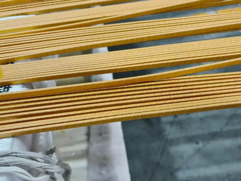
Basics of Fiberglass Covered Wire
Structure of Fiberglass Covered Wire
Fiberglass covered enameled wire typically consists of four parts from inside to outside: conductor (copper or aluminum), insulating enamel film (optional base layer), glass fiber braided layer, and impregnating resin or varnish. The conductor is generally round or flat copper wire, or aluminum conductor. The insulating enamel film provides the main electrical insulation in structures with a base layer. Glass fiber uses electrical-grade continuous filament glass yarn, providing mechanical protection and a heat-resistant framework. Impregnating resin or varnish (such as polyester-imide, silicone, etc.) bonds the glass fiber layer after curing and provides additional insulation.
Working Principle
The fiberglass covering provides insulation protection through the synergistic effect of glass fiber and impregnating varnish. Glass fiber itself has excellent heat resistance, withstanding temperatures up to several hundred degrees Celsius. Impregnating varnish fills the gaps between glass fibers, forming a dense insulation layer. When temperature rises, glass fiber and impregnating varnish together form a protective layer, preventing heat from conducting to the conductor. Even if the enamel film ages at high temperatures, the glass fiber framework still maintains mechanical integrity.
Historical Background
Glass fiber as an industrial material was invented in 1938 by Russell Games Slayter, originally used as insulation material. With the development of the electrical industry, fiberglass was gradually introduced into the winding wire insulation field. Early fiberglass covered wire was mainly used in high-temperature special applications. With process progress and cost reduction, the application range of fiberglass covered wire continues to expand, and it has now become a standard material in traction motors, wind power generation, new energy vehicles, and other fields.
Thermal Class of Fiberglass Covered Wire
Common Thermal Classes
| Class | Temperature | Impregnating Varnish | Application |
|---|---|---|---|
| Class B | 130°C | Standard varnish | General motors |
| Class F | 155°C | Modified polyester | Base grade |
| Class H | 180°C | Polyester-imide / silicone | Most widely used |
| Class 200 | 200°C | Silicone / PAI | High-temperature |
| Class 220+ | 220°C+ | Special high-temp | Extreme temperature |
Common thermal classes of fiberglass covered enameled wire mainly depend on the heat resistance of the impregnating varnish.
Features of Class 180 Fiberglass Paper-Covered Flat Copper Wire
Class 180 fiberglass paper-covered flat copper wire is currently one of the most widely used fiberglass covered wires. This product uses polyester-imide impregnating varnish or silicone resin varnish, with a heat resistance class of 180°C. Advantages of Class 180 products include: excellent heat resistance, capable of long-term operation in high-temperature environments; high mechanical strength, with glass fiber layer providing good wear resistance; stable electrical insulation, high breakdown voltage; wide applicability, compatible with most winding applications.
Selection Principles for Thermal Class
Selection of thermal class needs to consider the following factors: maximum working temperature of the equipment, temperature rise margin, safety factor, and industry standard requirements. General recommendation: equipment maximum working temperature plus 20-30°C temperature rise margin, plus 10-15°C safety factor, as a reference for choosing the thermal class. For example, if the equipment maximum working temperature is 150°C, after temperature rise margin it becomes 170-180°C, plus safety factor, recommend choosing Class H (180°C) fiberglass covered wire.
Conductor Specifications of Fiberglass Covered Wire
Round Wire Specifications
The conductor diameter range of fiberglass covered round copper wire is typically 0.50-5.00mm. Smaller diameters are easier to wind, while larger diameters are suitable for high-power applications. Round wires are divided by diameter into fine wire (≤0.50mm), medium wire (0.50-2.00mm), and coarse wire (≥2.00mm). Fiberglass covered wires of different diameters are suitable for different scenarios.
Flat Wire Specifications
The conductor size of fiberglass covered flat copper wire (also called fiberglass covered enamelled flat copper wire) is marked as width × thickness. Common specification range: width 1.00-10.00mm, thickness 0.80-5.00mm. Flat wire has the following advantages over round wire: high space utilization, suitable for compact designs; large heat dissipation area, low temperature rise; high mechanical strength, suitable for large windings.
Size Comparison Table for Fiberglass Covered Rectangular Copper Wire
Fiberglass covered rectangular copper wire has standardized size comparison tables, including multiple thickness options from 0.80mm to 5.60mm, with rich width selections that can be flexibly combined.
Standard System for Fiberglass Covered Wire
IEC Standards
IEC 60317 series standards are the most important international standards for fiberglass covered wire: IEC 60317-31:2015: Glass fiber wound resin or varnish impregnated bare or enamelled rectangular copper wire standard. IEC 60317-61:2012: Polyester glass fiber wound round copper wire, Class 180 minimum standard. IEC 60317-59:2015: Polyamide-imide enamelled round copper wire, Class 240 standard.
China Standards
China GB/T 7672 series standards correspond to IEC 60317 series: GB/T 7672.5-2008: Class 200 varnished glass fiber covered copper flat wire and glass fiber covered enamelled copper flat wire. GB 6109.1-90: General technical requirements for enamelled round wire, equivalently adopting IEC 317 (1988).
NEMA Standards
NEMA MW1000-2018 standard specifies technical requirements for glass fiber covered magnet wire (glass fiber covered, bare or film-insulated round copper magnet wire), including Class 155 glass fiber covered round copper magnet wire.
Standard Selection
Different industries and regions adopt different standards. International projects usually refer to IEC standards. North American projects refer to NEMA standards. China domestic market refers to GB standards.
Key Properties of Fiberglass Covered Wire
Electrical Properties
The main electrical properties of fiberglass covered wire include: breakdown voltage, insulation resistance, dielectric loss factor, partial discharge level. The breakdown voltage of fiberglass covered wire is higher than plain enamelled wire, generally reaching above 1500V. Insulation resistance is high, with good long-term working stability. Dielectric loss factor is low, suitable for high-frequency applications.
Mechanical Properties
Fiberglass covered wire has excellent mechanical properties: strong wear resistance, with glass fiber layer providing good surface protection; good impact resistance, with glass fiber layer absorbing impact energy; moderate flexibility, can be wound into complex shapes; good bending performance, suitable for embedded windings.
Thermal Properties
Thermal properties are the core advantage of fiberglass covered wire: long-term working temperature can reach 180°C (Class H) or 200°C; strong short-term overload capacity, can withstand higher thermal shock; long thermal aging life, can reach more than 20 years.
Environmental Resistance
Fiberglass covered wire also has the following environmental adaptability: good oil resistance, suitable for oil-immersed transformers; good chemical resistance, can resist most chemical corrosion; excellent moisture and heat resistance, suitable for humid environments.
Application Fields of Fiberglass Covered Wire
Motor Applications
Fiberglass covered wire is widely used in motors: Traction motors: for rail transit, electric vehicles, etc. Wind turbines: for large wind power generation units. Industrial motors: for high-temperature, high-load industrial environments. Household appliance motors: for air conditioners, washing machines, etc.
Transformer Applications
Fiberglass covered wire is mainly used in transformers for: high-temperature windings of oil-immersed transformers; heat-resistant windings of dry-type transformers; high-frequency windings of special transformers.
Power Generation Equipment
Applications of fiberglass covered wire in power generation equipment include: stator windings of hydroelectric generators; key windings of thermal generators; high-reliability windings of nuclear power equipment.
Aerospace and Defense
The aerospace and defense fields have extremely high requirements for material reliability. Fiberglass covered wire is used in key applications such as aviation motors, ship motors, and military electronic equipment due to its excellent heat resistance and mechanical properties.
New Energy Applications
With the rapid development of the new energy industry, demand for fiberglass covered wire is growing in the following areas: new energy vehicle drive motors, wind turbine generators, solar inverter reactors, energy storage equipment transformers.
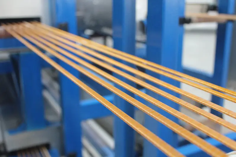
Selection Factors for Fiberglass Covered Wire
Temperature Class Selection
Temperature class is the primary factor in selecting fiberglass covered wire. Determined comprehensively based on the equipment’s maximum working temperature, temperature rise characteristics, and safety factor. General principle: equipment working temperature + 20-30°C (temperature rise margin) + 10-15°C (safety factor) = fiberglass covered wire thermal class.
Conductor Material Selection
The conductor of fiberglass covered wire is mainly copper and aluminum. Copper conductor has excellent conductivity, suitable for high-efficiency and small-size applications. Aluminum conductor is lightweight and low cost, suitable for weight-sensitive occasions.
Conductor Specification Selection
Factors for conductor specification selection: rated current (determines cross-sectional area), slot fill rate (determines size after insulation), mechanical strength (determines diameter lower limit), cost (affects total cost).
Insulation Structure Selection
Fiberglass covered wire has multiple insulation structure options: single-layer glass fiber covering, double-layer glass fiber covering, glass fiber + enamel composite, glass fiber + film composite. Complex structures provide higher insulation class and mechanical strength, but also increase cost and size.
Impregnating Varnish Selection
The choice of impregnating varnish affects the heat resistance class of fiberglass covered wire. Common impregnating varnishes include: polyester varnish (Class 130-155), polyester-imide varnish (Class 180), silicone varnish (Class 180-200), polyamide-imide varnish (Class 200 and above).
Selection Decision Method
Step 1: Determine Temperature Class
First clarify the equipment’s maximum working temperature and temperature rise characteristics. According to the rule of thumb: fiberglass covered wire thermal class = equipment working temperature + 20-30°C + safety factor.
Step 2: Determine Conductor Material
Choose conductor material based on application scenario. High-efficiency compact applications choose copper conductor. Weight-sensitive applications choose aluminum conductor. Cost-sensitive applications choose aluminum conductor or copper-clad aluminum.
Step 3: Determine Conductor Specification
Calculate required cross-sectional area based on rated current. Determine maximum allowable diameter based on winding space. Determine minimum allowable diameter based on mechanical requirements.
Step 4: Determine Insulation Structure
Choose insulation structure based on voltage class and reliability requirements. Ordinary applications choose single-layer glass fiber covering. High-voltage applications choose double-layer glass fiber covering or glass fiber + enamel composite structure.
Step 5: Determine Impregnating Varnish
Choose matching impregnating varnish based on temperature class. Class 130-155 choose polyester varnish. Class 180 choose polyester-imide or silicone varnish. Class 200 and above choose special high-temperature resistant varnish.
Step 6: Cost Evaluation
Under the premise of meeting performance requirements, optimize cost. Standard specifications have the lowest cost. Special specifications have higher cost. Bulk purchasing has discounts.
Common Misconceptions About Fiberglass Covered Wire
Misconception 1: Higher Class is Always Better
Many users believe that the higher the class of fiberglass covered wire, the better. In fact, overdesign causes cost waste. Appropriate class should be selected based on actual needs.
Misconception 2: Thicker Glass Fiber Layer is Always Better
The thicker the glass fiber layer, the better the insulation performance, but at the same time the larger the size, the worse the heat dissipation, and the higher the cost. An appropriate thickness of glass fiber layer should be selected.
Misconception 3: Ignoring the Role of Impregnating Varnish
Impregnating varnish plays a key role in fiberglass covered wire, determining the final thermal class. Ignoring the choice of impregnating varnish will result in thermal class not meeting requirements.
Misconception 4: Thicker Conductor is Always Better
The thicker the conductor, the larger the current carrying capacity, but cost and size also increase. The most economical conductor specification that meets current requirements should be selected.
Quality Control Points
Appearance Inspection
The appearance of fiberglass covered wire should be uniform, without damage or contamination. Glass fiber braiding should be tight, without looseness. Impregnating varnish layer should be uniform, without bubbles.
Dimensional Inspection
Conductor diameter, glass fiber layer thickness, total outer diameter should comply with standard requirements. Dimensional deviation should be within allowable range.
Performance Testing
Key performance tests include: breakdown voltage test, heat resistance test, bending test, wear resistance test, oil resistance test.
Supplier Evaluation
When choosing fiberglass covered wire suppliers, consider: production capacity, quality control system, technical support capability, delivery capability, price competitiveness.
Development Trends of Fiberglass Covered Wire
Temperature Class Improvement
With the continuous increase in power density of electrical equipment, the requirements for the temperature class of winding wires are also increasing. The application of Class 200 and Class 220 fiberglass covered wire will be more extensive.
Environmental Trend
Environmental regulations are driving fiberglass covered wire towards solvent-free and water-based development. New environmentally friendly impregnating varnishes are being developed and applied.
New Energy Driven
The rapid development of new energy vehicles, wind power generation, energy storage, and other new energy fields will drive significant growth in demand for fiberglass covered wire.
Intelligent Manufacturing
The production of fiberglass covered wire is developing towards intelligence and automation. Advanced online testing and process control technologies improve product quality.
Case Analysis
Case 1: Traction Motor Selection
A rail transit traction motor operates at 155°C with high current density and severe vibration. Recommended solution: Class H (180°C) fiberglass covered flat copper wire, conductor size determined by power, glass fiber + silicone resin varnish insulation structure.
Case 2: Wind Turbine Selection
A large wind turbine operates at 130°C and requires a 20-year life. Recommended solution: Class F (155°C) or Class H (180°C) fiberglass covered round copper wire, conductor diameter 2.0-3.0mm, double-layer glass fiber covering structure.
Case 3: Dry-type Transformer Selection
A dry-type transformer operates at 155°C with a voltage class of 10kV. Recommended solution: Class H (180°C) fiberglass covered enamelled flat copper wire, conductor size determined by power, glass fiber + polyester-imide varnish insulation structure.
Summary
Fiberglass covered enameled wire is a key material for high-temperature winding applications. Choosing the right fiberglass covered wire requires comprehensive consideration of multiple factors including temperature class, conductor material, conductor specification, insulation structure, and impregnating varnish. Temperature class is the primary consideration and should be determined based on equipment working temperature, temperature rise characteristics, and safety factor. Conductor material and specification need to be determined based on current, space, and mechanical requirements. Insulation structure needs to be determined based on voltage class and reliability requirements. Impregnating varnish determines the actual heat resistance performance of fiberglass covered wire. With electrical equipment developing towards high power density and high reliability, the application prospects of fiberglass covered wire are broad. Engineers should comprehensively consider performance, cost, reliability, and other factors based on specific application scenarios to choose the most suitable fiberglass covered enameled wire product.