


Introduction
Variable frequency capacitors are key energy storage components in power electronic equipment such as variable frequency drives (VFD), uninterruptible power supplies (UPS), PV inverters, wind power converters, and electric vehicle drives. Unlike traditional line-frequency capacitors, variable frequency capacitors operate in high-frequency PWM (Pulse Width Modulation) environments, withstanding the combined effects of high-frequency pulse currents, high voltage stress, and temperature rise.
Variable frequency capacitors are mainly classified into four types by application: DC-Link capacitors (supporting the DC bus), output filter capacitors (suppressing common-mode/differential-mode interference), resonant capacitors (used in resonant soft-switching circuits), and snubber capacitors (protecting power semiconductor devices). Core functions of these capacitors in variable frequency systems include: stabilizing DC bus voltage, smoothing ripple current, filtering high-frequency harmonics, and reducing switching losses.
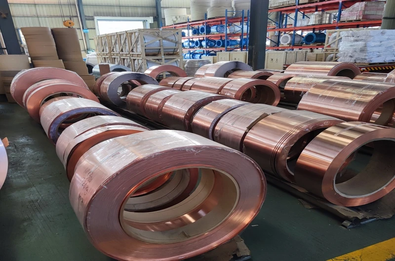
Copper foil as electrode material for variable frequency capacitors—its electrical conductivity, thickness uniformity, and surface quality directly determine the capacitor’s equivalent series resistance (ESR), ripple current carrying capacity, long-term reliability, and lifespan. This article systematically explains key parameters, selection criteria, and industrial applications for copper foil used in variable frequency capacitors, serving as a professional reference for variable frequency capacitor manufacturers and procurement personnel.
1. Variable Frequency Capacitor Structure and Copper Foil Principles
1.1 Basic Structure of Variable Frequency Capacitors
Variable frequency capacitors typically use metallized film capacitor structure or metal foil capacitor structure.
Metal foil capacitors: Use copper foil or aluminum foil as electrodes, alternating with dielectric film (polypropylene, polyester, or polyphenylene sulfide) through winding or lamination. Copper foil as an independent conductor layer has large electrode cross-sectional area and strong conductivity, capable of withstanding large ripple current, and is the mainstream structure for high-power variable frequency capacitors.
Metallized film capacitors: Vacuum deposit a thin layer of metal (aluminum or zinc) on the dielectric film surface as electrodes. Small in size with good self-healing performance, but limited ripple current carrying capacity, mainly used for small to medium power applications.
For high-power DC-Link capacitors and resonant capacitors in variable frequency systems, metal foil structure is preferred, with copper foil electrodes serving as critical current paths.
1.2 Core Role of Copper Foil in Variable Frequency Capacitors
Copper foil as electrode material for variable frequency capacitors bears the following key functions:
Current conduction: Variable frequency capacitors need to withstand large ripple current (typically from tens to hundreds of amperes), and copper foil’s low resistance characteristics ensure current conduction efficiency.
ESR reduction: ESR (equivalent series resistance) directly affects the capacitor’s ripple current carrying capacity and heat generation. Copper foil’s low resistivity (1.7×10⁻⁸Ω·m) enables capacitors to have lower ESR.
Thermal dissipation: Variable frequency capacitors generate significant heat during operation, and copper foil’s good thermal conductivity helps rapid heat dissipation.
Mechanical support: During winding or lamination processes, copper foil provides necessary mechanical strength, ensuring capacitor structural stability.
1.3 Comparison of Copper Foil and Aluminum Foil Electrodes
In variable frequency capacitors, copper foil and aluminum foil electrodes each have their applications:
Copper foil electrodes: Excellent electrical conductivity (conductivity approximately 101% IACS), strong large ripple current carrying capacity, low ESR, good temperature resistance (can work above 200°C), high mechanical strength. Suitable for high-power, high ripple current variable frequency applications.
Aluminum foil electrodes: Low cost, light weight (density only 30% that of copper), but inferior electrical conductivity compared to copper foil (conductivity approximately 61% IACS), higher ESR. Suitable for cost-sensitive, low ripple current applications.
For high-power variable frequency systems such as VFD, PV inverters, and wind power converters, copper foil electrodes are the better choice.
2. Key Specifications and Technical Requirements
2.1 Copper Foil Purity
Copper foil purity directly affects variable frequency capacitor electrical performance, loss, and lifespan.
T2 pure copper (99.9%): The most commonly used industrial pure copper, suitable for most variable frequency capacitor applications, with optimal cost-performance ratio.
Oxygen-free copper (OFHC, 99.99%): Extremely low impurity content, better electrical conductivity (above 101% IACS), suitable for high-end variable frequency capacitors with extremely high efficiency requirements.
Impurity effects: Impurities such as iron, sulfur, and oxygen will reduce copper foil electrical conductivity and may affect capacitor stability under high temperature working conditions. In high-power, high temperature application scenarios, it is recommended to select products with strictly controlled impurity content.
2.2 Thickness Selection
Copper foil thickness is the key parameter determining variable frequency capacitor ripple current carrying capacity and ESR.
Thin copper foil (9μm–18μm): Suitable for small-capacity, low ripple current variable frequency capacitors. Thin copper foil is soft and easy to bend, suitable for precision winding processes.
Medium copper foil (18μm–35μm): The mainstream specification for variable frequency capacitors, balancing conductivity and mechanical strength, suitable for medium ripple current applications.
Thick copper foil (35μm–100μm and above): Suitable for large ripple current, high voltage variable frequency applications. Thick copper foil has large cross-sectional area, low ESR, and can withstand greater ripple current.
Selection advice: Copper foil thickness selection for variable frequency capacitors needs comprehensive consideration of rated voltage, capacitance, ripple current peak, ESR requirements, and winding processes. In high-power VFD applications, copper foil thickness is typically selected above 35μm.
2.3 Width and Dimensions
Copper foil width needs to match dielectric film width and capacitor structural design.
Standard width range: Customizable according to customer requirements; common coil widths range from tens of millimeters to hundreds of millimeters.
Width precision: Copper foil width tolerance should be strictly controlled (usually within ±0.1mm) to ensure smooth winding and capacitance value consistency.
Coil quality: Copper foil should be free from wrinkles and ripples, with neat end faces, ensuring stable product quality in continuous production.
2.4 Annealing State
Copper foil annealing state affects its mechanical properties and processing performance.
Hard state copper foil: High tensile strength (300–380MPa), low elongation (3–8%), suitable for high-speed automatic winding, with good electrode dimensional stability. Most variable frequency capacitor manufacturers use hard state copper foil.
Soft state copper foil: Soft and easy to bend (elongation 20–40%), suitable for applications requiring subsequent bending or complex forming.
Selection advice: Hard or half-hard state copper foil is the preferred choice for variable frequency capacitor automatic winding processes.
2.5 Surface Quality Requirements
Variable frequency capacitors have strict requirements for copper foil surface quality, as surface defects may cause local electric field concentration, overheating, or even breakdown.
Surface roughness: Ra is usually required below 0.8μm; smooth surface facilitates tight bonding with dielectric film, reducing partial discharge risk.
Thickness uniformity: Copper foil thickness tolerance should be controlled within ±5%; for high-power applications, it is recommended to control within ±3%.
Surface cleanliness: Copper foil surface should be free from oil contamination, oxide film, dust, and other impurities. Small defects may cause serious problems in high-frequency high-voltage environments.
Edge quality: Copper foil edges should be neat, free from burrs or tears, avoiding dielectric film damage during winding.
3. Insulation Class and Temperature Management
3.1 Effect of Temperature on Variable Frequency Capacitors
Variable frequency capacitors typically work in higher temperature environments; core temperature rise sources include:
Ripple current heating: ESR × I²_ripple losses are the main heat source.
Switching losses: Dielectric losses caused by high-frequency PWM switching.
Ambient temperature: Internal ambient temperature of variable frequency drives is typically high (60–80°C), requiring derating consideration.
Copper foil thickness and conductivity directly affect capacitor ESR and heat generation. Thicker copper foil can reduce ESR and heat generation.
3.2 Insulation Class and Selection
| Insulation Class | Max Operating Temperature | Application Scenarios | Copper Foil Selection |
|---|---|---|---|
| Class B | 130°C | General line-frequency variable frequency applications | Soft/half-hard + polyester insulation |
| Class F | 155°C | Standard variable frequency drives, UPS | Hard + polyesterimide insulation |
| Class H | 180°C | High-power VFD, rail transit | Hard + polyamide-imide insulation |
| Class C | Above 200°C | Extreme high temperature variable frequency applications | Hard + special high temperature insulation |
Selection calculation: Design Temperature = Ambient Temperature + Temperature Rise + Safety Margin (20–25°C). For example: at 60°C ambient temperature, if temperature rise is 80°C plus 25°C margin, design temperature is 165°C, and Class H insulation should be selected.
3.3 Dielectric Film Selection
Common dielectric films used in variable frequency capacitors and their characteristics:
Polypropylene film (PP): Extremely low loss (tanδ<0.0005), high insulation resistance, the preferred dielectric material for high-power DC-Link capacitors and high-frequency resonant capacitors. Temperature resistance approximately 105°C.
Polyester film (PET): Lower cost, good mechanical strength, temperature resistance up to 150°C, suitable for small to medium power variable frequency applications.
Polyphenylene sulfide film (PPS): Excellent temperature resistance (above 200°C), good dimensional stability, suitable for high temperature variable frequency environments.
Polyethylene naphthalate film (PEN): Excellent comprehensive performance, temperature resistance approximately 155°C, an emerging high-end dielectric material.
4. Industrial Applications and Selection Recommendations
4.1 Industrial Variable Frequency Field
Variable frequency drives (VFD): The largest application market for variable frequency capacitors. In VFDs, DC-Link capacitors, output filter capacitors, and resonant capacitors all need to use metal foil electrode metallized film capacitors.
Small to medium power VFD (≤50kW): Usually use copper foil electrode capacitors with 18μm–35μm thickness.
High-power VFD (50kW–MW level): Use 35μm–100μm thick copper foil electrode capacitors, with Class H or C insulation and forced air/water cooling.
4.2 New Energy Field
PV inverters: Need high-power, long-lifespan DC-Link capacitors and filter capacitors. Copper foil electrode thickness is usually selected 25μm–50μm, with Class F or H insulation.
Wind power converters: Harsh working environments (high temperature, vibration, wide temperature range), need high-reliability variable frequency capacitors. Recommended: hard state thick copper foil (above 50μm) with Class H insulation and epoxy impregnation solution.
Energy storage converters (PCS): Extremely high requirements for capacitor ripple current carrying capacity and lifespan.
4.3 Electric Vehicle Field
Motor controllers (MCU): Use high-frequency DC-Link capacitors, operating frequency can reach tens of kHz. Recommended: thin copper foil (18μm–35μm) with low-loss polypropylene film.
On-board chargers (OBC): Need high-efficiency, miniaturized capacitors, with strict requirements for ripple current and loss.
DC-DC converters: High-frequency working environment imposes higher requirements on copper foil high-frequency characteristics.
4.4 Rail Transit Field
Traction converters: Need long-term reliable operation in harsh environments, using high-voltage, large-capacity DC-Link capacitors. Recommended: hard state thick copper foil (50μm–100μm) with Class H insulation and reliable mechanical fixing structure.
Auxiliary inverters: High requirements for capacitor reliability and lifespan (usually requiring 20+ years).
4.5 Common Selection Problems and Solutions
Capacitor overheating: Check if copper foil thickness is sufficient (whether ESR is too high); confirm if thermal dissipation design is reasonable (whether air/water cooling is adequate); consider increasing copper foil thickness or selecting lower ESR design.
Insufficient ripple current: Check if copper foil cross-sectional area meets ripple current requirements; confirm copper foil electrical conductivity; consider using thick copper foil or multi-layer parallel design.
Early capacitor failure: Check if copper foil surface quality is qualified; confirm insulation class and working temperature match; consider using higher specification copper foil.
Excessive high-frequency loss: Select low-loss dielectric film (such as polypropylene); use thin copper foil to reduce skin effect impact; consider copper foil surface treatment to reduce contact resistance.
5. Supplier Selection and Quality Control
5.1 Quality Certifications
ISO9001 quality management system certification is the basic requirement. For automotive-grade applications, IATF16949 certification is required. Environmental certifications such as RoHS and REACH are necessary for exporting to overseas markets.
5.2 Technical Capability Evaluation
Custom drawing capability: Whether copper foil thickness, width, and tolerance range can meet design requirements. Whether sample development cycle is reasonable (typically 5–10 working days).
Process quality control: Whether key control capabilities such as thickness testing, surface quality testing, and purity testing are available. Whether on-site supervision is supported.
5.3 Production Capacity and Delivery
Stable production capacity is the guarantee for long-term supply. It is recommended to select suppliers with monthly production capacity above 100 tons and complete quality control systems.
6. Product Specifications Summary
| Parameter | Specification Range |
|---|---|
| Copper Foil Purity | 99.9% – 99.99% |
| Thickness | 9μm – 100μm |
| Width | 10mm – 500mm |
| State | Hard / Half-hard |
| Surface Roughness | Ra≤0.8μm |
| Thickness Tolerance | ±3% – ±5% |
| Standards | IEC / GB / JIS / IEEE |
7. Technical Support and Contact
For detailed product specifications, samples, or technical selection support, please contact Zhengzhou LP Industry Co., Ltd. With years of expertise in electronic copper materials exports, our copper foil products are widely used in variable frequency capacitors, film capacitors, power electronics, and other fields.
- Email: office@cnlpzz.com
- Phone/WhatsApp: 0086-19337889070
- Key Products: Copper foil, Electrode copper foil, Variable frequency capacitor materials
This document provides professional guidance for copper foil selection in variable frequency capacitor applications. For specific projects, please consult with technical professionals based on actual operating conditions.