


Introduction
Wireless charging technology has become a standard configuration for modern electronic devices, from smartphones and smartwatches to electric vehicles. The convenience brought by wireless charging is deeply appreciated by consumers. The core principle of wireless charging is electromagnetic induction coupling—energy is transferred between the transmitter coil and receiver coil through a magnetic field, achieving electrical energy transmission without physical connection.
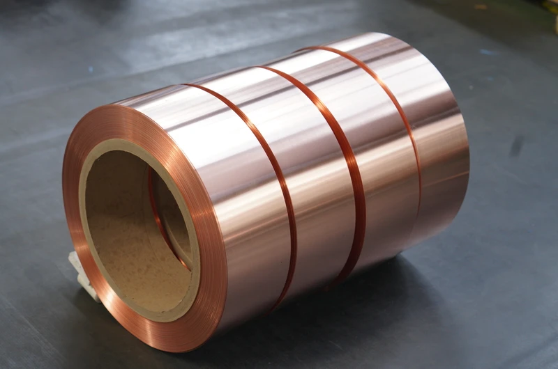
With its excellent electrical conductivity, precision processing characteristics, and good thermal dissipation capability, copper foil has become the ideal material for wireless charging coil manufacturing. Compared to traditional round wire winding, copper foil coils offer lower resistance, higher fill factor, and more precise magnetic field distribution characteristics, effectively improving wireless charging efficiency and power density.
This article systematically explains key parameters, selection criteria, and industrial applications for copper foil used in wireless charging coils, serving as a professional reference for engineers and procurement personnel.
1. Wireless Charging Principles and Advantages of Copper Foil
1.1 Basic Principles of Wireless Charging
Wireless charging is mainly based on the principle of electromagnetic induction, also known as inductive coupling wireless charging. The transmitter (TX) coil is energized with high-frequency alternating current, generating an alternating magnetic field around the coil; the receiver (RX) coil is within this magnetic field, generating induced current through electromagnetic induction, which is then rectified and filtered to charge the battery.
Key parameters of wireless charging include: charging power (ranging from 5W to hundreds of W), charging efficiency (typically between 75% and 95%), transmission distance (from a few millimeters to a few centimeters), and alignment accuracy requirements. Different application scenarios have different priority requirements for these parameters.
According to the Qi standard (the most widely adopted wireless charging standard globally), the transmitter and receiver need to complete handshake protocol, power negotiation, status monitoring and other communication processes to ensure safe and reliable charging.
1.2 Advantages of Copper Foil in Wireless Charging Coils
Compared to traditional round wire winding, copper foil offers the following significant advantages in wireless charging coil manufacturing:
Lower resistance loss: As a flat conductor, copper foil has larger cross-sectional area and shorter conductive path. Compared to round wire with the same cross-sectional area, copper foil coils have lower DC resistance, reducing I²R losses and improving charging efficiency. In high-power wireless charging, the efficiency improvement from reduced resistance is particularly significant.
Higher fill factor: Flat copper foil can be more tightly arranged on the coil former, fully utilizing effective space. For consumer electronics with limited space, high fill factor means more conductor can be placed in the same volume, thereby reducing resistance or improving power density.
More uniform magnetic field distribution: Wireless charging efficiency is closely related to magnetic field coupling between transmitter and receiver. The flat shape of copper foil helps optimize coil magnetic field distribution, improving magnetic field uniformity and coupling efficiency.
Superior thermal dissipation performance: Flat copper foil has larger contact area with air or thermal dissipation medium, allowing heat to dissipate more quickly. This is particularly important for high-power wireless charging; effective thermal management design can support higher continuous power output.
More precise inductance control: Copper foil thickness and width tolerances can be precisely controlled, facilitating accurate coil inductance value implementation. This is particularly important for resonant wireless charging (operating at high frequencies), which requires precise resonant frequency matching.
1.3 Main Types of Wireless Charging Coils
A11/A11a coils: The most common smartphone wireless charging coils, belonging to transmitter coils. Typical structure is single-layer or double-layer planar spiral coil, with copper foil thickness typically 0.1–0.2mm.
Multi-coil solutions: To expand charging area or achieve position-independent charging, multiple coil array layouts are adopted. Copper foil can be processed into various shapes, flexibly adapting to different coil array designs.
Automotive wireless charging coils: High-power wireless charging devices installed inside vehicles, with power reaching 15W or higher. Requires larger coil area and better thermal dissipation design.
Electric vehicle wireless charging coils: Used for static or dynamic wireless charging of electric vehicles, with power ranging from 3kW to tens of kW. Large coil size and high current impose special requirements on copper foil thickness and width.
2. Key Specifications and Technical Requirements
2.1 Thickness Selection
Copper foil thickness is the core parameter determining wireless charging coil resistance, heat generation, and power-carrying capacity.
Thin copper foil (0.05–0.10mm): Suitable for small-power consumer electronics (5W–15W) wireless charging coils. Thin copper foil is soft and easy to bend, suitable for precision coil winding, with lower cost.
Medium copper foil (0.10–0.20mm): Suitable for medium-power (15W–50W) wireless charging applications, such as tablets and laptops. This thickness range balances conductivity and processing cost.
Thick copper foil (0.20–0.30mm and above): Suitable for high-power wireless charging, such as electric vehicle charging stations. Thick copper foil has large cross-sectional area and low resistance, effectively reducing heat issues from high current.
Selection advice: Wireless charging coil operating frequencies are typically 100–300kHz (Qi standard) or higher (AirFuel standard). At these frequencies, the skin effect of copper foil must be considered—current tends to flow along the conductor surface. The actual effective conductive cross-sectional area is smaller than the geometric cross-sectional area. Thinner copper foil may actually have higher effective utilization at high frequencies.
2.2 Width and Shape
Copper foil width directly affects coil end length and fill factor.
Standard width specifications: 3mm, 5mm, 8mm, 10mm, 15mm, 20mm, etc., with custom wider or narrower specifications available.
Width selection principle: Width should match the coil former and magnetic core structure. Wide copper foil can reduce conductor usage and resistance, but may increase coil size and cost. Narrow copper foil is more suitable for precision coil design.
Coil shape: Copper foil can be wound into different shapes such as round, square, rectangular, and oval. Specific selection depends on application space constraints and magnetic field distribution requirements.
2.3 Purity and Conductivity
Copper foil purity directly affects coil electrical conductivity and thermal stability.
T2 pure copper (99.9%): Conductivity approximately 98% IACS, the most commonly used industrial pure copper, suitable for the vast majority of wireless charging coil applications, best cost-effectiveness.
Oxygen-free copper (OFHC, 99.99%): Conductivity can reach above 101% IACS, with extremely low impurity content, suitable for precision applications with extremely high efficiency requirements.
Selection advice: General consumer electronics wireless charging can use T2 pure copper. For high-power or thermally demanding applications, oxygen-free copper can be considered to further reduce resistance.
2.4 Annealing State Selection
The annealing state of copper foil affects its flexibility and processing performance.
Soft state copper foil (O): Tensile strength 200–260MPa, elongation 20–40%. Soft state copper foil is very soft and easy to bend into complex shapes, suitable for precision coil manual or semi-automatic winding.
Half-hard state copper foil (H02/H04): Tensile strength 260–300MPa, elongation 8–15%. Half-hard state copper foil has both certain formability and mechanical strength, suitable for fully automatic winding machine processing.
Selection advice: Consumer electronics small coils mostly use soft state copper foil for precision forming; high-power industrial coils can use half-hard state for automated production.
2.5 Surface Quality Requirements
Wireless charging coils have strict requirements for copper foil surface quality, directly affecting charging efficiency and reliability.
Surface roughness: Ra≤0.8μm, smooth surface facilitates uniform insulation varnish film adhesion and reduces eddy current losses for high-frequency current.
Thickness uniformity: Copper foil thickness tolerance should be controlled within ±5%, ensuring consistent coil turn resistance and stable inductance value.
Surface defects: Cracks, folds, oil contamination and other defects are strictly prohibited. Small defects in high-frequency alternating magnetic fields may cause local overheating or insulation failure.
3. Temperature Resistance and Insulation Selection
3.1 Effect of Temperature on Wireless Charging Coils
During wireless charging, coils generate heat due to resistance losses. For every 10°C increase in temperature, copper’s resistance increases by approximately 4%, forming a vicious cycle. Excessive temperature not only reduces charging efficiency but may also damage equipment or batteries.
Main sources of wireless charging coil temperature rise include: I²R loss heat from the coil itself, thermal conduction from nearby power devices, and ambient temperature influence.
Effective thermal management is key to achieving high-power wireless charging. Design needs to comprehensively consider coil resistance, thermal dissipation structure, and ambient temperature.
3.2 Insulation Class and Selection
| Insulation Class | Max Operating Temperature | Application Scenarios | Copper Foil Selection |
|---|---|---|---|
| Class B | 130°C | General consumer electronics, standard wireless charging | Soft + polyester insulation |
| Class F | 155°C | High-power charging, higher temperature rise | Soft/half-hard + polyesterimide insulation |
| Class H | 180°C | High power density or high-temperature environments | Half-hard + polyamide-imide insulation |
Selection calculation: Design Temperature = Ambient Temperature + Temperature Rise + Safety Margin (15–20°C). For example: at 25°C ambient temperature, if temperature rise is 40°C plus 20°C margin, design temperature is 85°C, and Class B insulation is sufficient.
3.3 Insulation Treatment Solutions
Enameled copper foil: Polyester varnish (PEW) with 130°C temperature resistance and best cost-effectiveness, the standard choice for consumer electronics wireless charging coils. Polyesterimide varnish (EIW) with 155°C temperature resistance, suitable for high-power wireless charging applications. Polyamide-imide varnish (AIW) with 200°C temperature resistance, suitable for harsh environments or applications with extremely high reliability requirements.
Cover film solution: Laminating insulating film (such as polyimide film) on the copper foil coil surface provides additional insulation protection and mechanical support.
Overall molding: Using epoxy resin or silicone to encapsulate the entire coil achieves IP67 or higher protection rating. This solution is widely used in automotive-grade wireless charging modules.
4. Industrial Applications and Selection Recommendations
4.1 Consumer Electronics Field
Smartphone wireless charging: This is currently the largest application market for wireless charging. Under the Qi standard, power has evolved from 5W to 15W and beyond. Coil copper foil thickness is typically 0.08–0.15mm, using soft state T2 copper foil with polyester insulation.
Smartwatch/earbuds charging: These devices are compact in size, typically using small coils and lower charging power. Coil copper foil thickness of 0.05–0.10mm is sufficient.
Tablets/laptops: Require larger charging area and higher power, with more complex coil designs. Copper foil thickness typically 0.10–0.20mm, possibly requiring multi-coil combined designs.
4.2 Automotive Field
Vehicle wireless charging: Installed in automotive center consoles or armrests to charge phones and other devices. Power ranges from 5W to 15W. Automotive environments have high reliability requirements, needing to pass strict temperature, vibration, and EMC tests. Recommended: Class F insulated copper foil coils with overall molding process.
Electric vehicle wireless charging: An important direction for wireless charging technology development. Static wireless charging power ranges from 3.3kW to 11kW, possibly reaching tens of kW in the future. Large coil size and high current impose higher requirements on copper foil thickness and mechanical strength. Recommended: hard or half-hard state copper foil, thickness 0.2–0.5mm, with Class H insulation and reliable mechanical fixing structure.
4.3 Industrial and Medical Fields
Industrial equipment wireless power supply: In some industrial scenarios where physical connection is difficult, wireless charging provides reliable power supply solutions. Higher requirements for copper foil coil reliability and durability.
Medical device wireless charging: Wireless charging for implantable medical devices or wearable medical equipment, with strict requirements for safety and biocompatibility. Coils need to be miniaturized and highly reliable, with strict medical certifications.
4.4 Common Selection Problems and Solutions
Low charging efficiency: Check if copper foil thickness is sufficient (whether resistance is too high); confirm if coil inductance value meets resonant frequency requirements; check alignment between transmitter and receiver.
Excessive coil temperature rise: Check if copper foil cross-sectional area is sufficient; confirm if insulation class meets thermal dissipation requirements; consider adding heat sinks or using better thermal conductive insulation materials; optimize thermal conduction paths in structural design.
Poor coil compatibility: Confirm compliance with Qi or other standard requirements; check if coil size and inductance value are within standard tolerances; ensure correct coil position and magnetic core configuration.
Reliability issues: Check if insulation treatment is adequate; consider using higher-grade insulation materials; add mechanical protection and vibration reduction measures in structural design.
5. Supplier Selection and Quality Control
5.1 Quality Certifications
ISO9001 quality management system certification is the basic requirement. For automotive and medical applications, relevant industry certifications such as IATF16949 and ISO13485 are also required.
5.2 Technical Capability Evaluation
Precision processing capability: Copper foil thickness and width tolerance control capability, especially for ultra-thin copper foil (less than 0.1mm) processing capability. Whether sample development cycle is reasonable (typically 5–7 working days).
Custom drawing: Whether supporting customization of various shaped coil copper foil according to customer drawings.
5.3 Production Capacity and Delivery
Stable production capacity is the guarantee for long-term supply. It is recommended to select suppliers with complete quality control systems.
6. Product Specifications Summary
| Parameter | Specification Range |
|---|---|
| Thickness | 0.05mm – 0.30mm |
| Width | 3mm – 30mm |
| Purity | 99.9% – 99.99% |
| State | Soft / Half-hard |
| Conductivity | 98% – 101% IACS |
| Temperature Range | -40°C – +200°C |
| Standards | IEC / GB / Qi / AirFuel |
7. Technical Support and Contact
For detailed product specifications, samples, or technical selection support, please contact Zhengzhou LP Industry Co., Ltd. With 30 years of expertise in electromagnetic wire exports, our copper foil products are widely used in wireless charging, smart home, automotive electronics, medical devices, and other emerging fields.
- Email: office@cnlpzz.com
- Phone/WhatsApp: 0086-19337889070
- Key Products: Enameled copper (aluminum) round wire, Enameled copper (aluminum) flat wire, Copper foil, Aluminum foil
This document provides professional guidance for copper foil selection in wireless charging coil applications. For specific projects, please consult with technical professionals based on actual operating conditions.