


Introduction
Choke coils (also called reactors) are indispensable fundamental components in power electronics, new energy, and industrial control fields. Their basic function is to achieve current filtering, energy storage, power factor correction, and harmonic suppression through inductive characteristics. In PV inverters, wind power converters, electric vehicle charging stations, UPS systems, and other equipment, choke coils directly affect system efficiency, reliability, and electromagnetic compatibility.
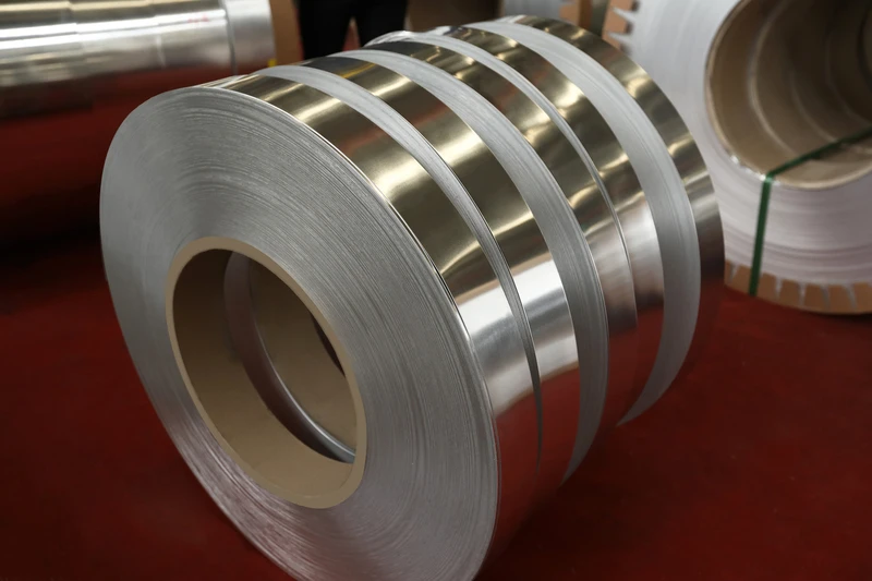
With its lightweight properties, cost advantages, and good processing performance, aluminum foil has become the ideal material for small to medium-power choke coil manufacturing. Compared to round aluminum wire, aluminum foil as a flat conductor offers larger heat dissipation area, higher fill factor, and better high-frequency characteristics, making it especially suitable for switching power supplies and power electronics fields.
This article systematically explains key parameters, selection criteria, and industrial applications for aluminum foil used in choke coils, serving as a professional reference for engineers and procurement personnel.
1. Working Principles of Choke Coils and Advantages of Aluminum Foil
1.1 Basic Principles of Choke Coils
A choke coil is essentially an inductor winding with an iron core. When current flows through the coil, magnetic energy is stored in the core. Inductance is proportional to the square of coil turns, core cross-sectional area, and permeability. Main functions of choke coils include:
Filtering function: In rectifier circuits, choke coils combined with filter capacitors can effectively smooth pulsating direct current and reduce ripple content. At the input and output terminals of switching power supplies, choke coils can suppress high-frequency noise and radio frequency interference.
Power factor correction: In AC circuits, choke coils can serve as the core component of power factor correction inductors, improving grid-side power factor and reducing reactive power transmission.
Harmonic suppression: In power distribution systems containing large nonlinear loads (such as frequency converters and rectifiers), choke coils can limit the propagation of harmonic currents and protect sensitive equipment.
Energy storage and release: In DC-DC converters of switching power supplies, choke coils store energy when switching transistors conduct and release energy when they turn off, achieving voltage conversion and current continuity.
1.2 Advantages of Aluminum Foil in Choke Coils
Compared to traditional round wire winding, aluminum foil offers the following significant advantages in choke coil manufacturing:
Higher fill factor: As a flat conductor, aluminum foil occupies less space at the same cross-sectional area. For power electronics equipment with limited space, high fill factor means more conductor can be accommodated in the same volume, thereby reducing resistance and improving current-carrying capacity.
Better thermal dissipation performance: Flat aluminum foil has much larger contact area with cooling medium than round wire; heat can dissipate more quickly to the surrounding environment. For high power density applications, good thermal dissipation performance is directly related to choke coil temperature rise and service life.
Superior high-frequency characteristics: In high-frequency switching power supply applications, choke coil operating frequencies can reach dozens of kHz to hundreds of kHz. The flat shape of aluminum foil helps reduce eddy current losses and improves high-frequency inductor conversion efficiency. Meanwhile, aluminum foil has less skin effect impact, making it more suitable for high-frequency applications.
More precise magnetic circuit control: Aluminum foil width and thickness tolerances can be made very precise, facilitating accurate inductance value and flux density control. This is particularly important for industrial applications requiring precise parameters.
Easier automated production: Aluminum foil can be processed using precision automatic winding equipment; coils are neatly arranged with good consistency, suitable for mass production.
1.3 Aluminum Foil vs Copper Foil Selection for Choke Coils
In choke coil manufacturing, copper foil and aluminum foil each have their applicable scenarios. Copper foil has better electrical conductivity and is suitable for high-current or extremely high-efficiency applications; aluminum foil dominates small to medium-power applications with its lightweight and cost advantages.
Main considerations for choosing aluminum foil include: cost-sensitive projects, weight-limited applications, occasions with high thermal dissipation requirements, and general industrial uses. In many PV inverters and new energy vehicle charging stations, aluminum foil choke coils have become the industry standard.
2. Key Specifications and Technical Requirements
2.1 Thickness Selection
Aluminum foil thickness is the core parameter determining choke coil inductance performance and current-carrying capacity.
Thin aluminum foil (0.03–0.10mm): Suitable for high-frequency switching power supply choke coils, precision filtering inductors, etc. Thin aluminum foil has lower high-frequency loss, suitable for high-frequency applications from dozens of kHz to hundreds of kHz. Meanwhile, thin aluminum foil is soft and easy to form, suitable for complex shape design.
Medium aluminum foil (0.10–0.25mm): Suitable for medium-power line-frequency or low-frequency choke coils, such as DC-Link inductors in PV inverters and filter reactors in wind power converters. This thickness range balances conductivity and mechanical processing.
Thick aluminum foil (0.25–0.50mm and above): Suitable for high-power low-frequency applications, such as high-current filter reactors and welding power supply storage inductors. Thick aluminum foil has large cross-sectional area, can carry higher current, and has higher mechanical strength.
Selection advice: Choke coil current ranges typically from several amperes to hundreds of amperes. Required cross-sectional area needs to be calculated based on design current, combined with operating frequency to determine aluminum foil thickness. High-frequency applications should prioritize thinner aluminum foil to reduce eddy current losses; high-current applications need thicker aluminum foil to reduce resistance.
2.2 Width and Shape
Aluminum foil width directly affects choke coil end dimensions and fill factor.
Standard width specifications: 5mm, 10mm, 15mm, 20mm, 30mm, 50mm, 80mm, 100mm, 120mm, 150mm, with custom wider or narrower specifications available.
Width selection principle: Width should match the magnetic core window dimensions, ensuring aluminum foil fits flat into the magnetic core air gap or slot. Width too large causes filling difficulty; width too small increases end dimensions and leakage reactance.
Special-shaped aluminum foil: Bent type, step type, notched type and other special-shaped aluminum foil can be customized according to drawings to optimize coil arrangement in the magnetic core, reduce end length, and improve space utilization.
2.3 Purity and Conductivity
Aluminum foil purity directly affects choke coil resistance loss and temperature rise characteristics.
1060 pure aluminum (99.6% aluminum content) is the most commonly used industrial aluminum material, with conductivity approximately 61% IACS, best cost-effectiveness, suitable for most small to medium-power choke coil applications.
1070 pure aluminum (99.7% aluminum content) has very close performance to 1060, with conductivity also approximately 61% IACS.
Selection advice: For choke coils in general industrial applications, 1060 or 1070 pure aluminum can meet requirements. If further reducing resistance or improving efficiency is needed, consider using copper foil with lower resistivity.
2.4 Annealing State Selection
The annealing state of aluminum foil affects its mechanical processing performance and final coil stability.
Soft state aluminum foil (O): Tensile strength 50–80MPa, elongation 20–35%. Soft state aluminum foil is very soft and easy to bend, suitable for choke coil designs requiring complex shapes or post-bending processing, also suitable for manual winding and small-batch trial production.
Half-hard state aluminum foil (H14/H16): Tensile strength 100–150MPa, elongation 3–8%. Half-hard state aluminum foil has both certain formability and mechanical strength, the ideal choice for automatic winding machine processing; most standard choke coils use this state.
Hard state aluminum foil (H18/H19): Tensile strength 150–200MPa, elongation 1–3%. Hard state aluminum foil has the strongest shape-holding ability and is not easily deformed, suitable for applications requiring high mechanical strength, or for high-speed winding processes with automatic winding machines.
Selection advice: If using automatic winding machines, half-hard is the best choice; if manual bending or complex forming is needed, select soft state; if extremely high dimensional stability is required, select hard state.
2.5 Surface Quality Requirements
Choke coils have specific requirements for aluminum foil surface quality to ensure insulation reliability and inductance stability.
Surface roughness: Ra≤1.0μm, ≤0.6μm recommended for high-frequency applications. Smooth surface facilitates uniform insulation varnish film adhesion and reduces local electric field concentration.
Thickness uniformity: Aluminum foil thickness tolerance should be controlled within ±5%, ensuring consistent coil resistance and stable inductance value. For precision filtering inductors, thickness tolerance requirements are more stringent.
Surface defects: Cracks, folds, inclusions, oil contamination, and other defects are strictly prohibited. Small defects in high-frequency high-electric field environments may cause partial discharge and reduce insulation life.
Residual stress: For precision applications, rolling residual stress in hard state aluminum foil may cause post-winding deformation. Stress relief annealing treatment or soft state aluminum foil is recommended.
3. Temperature Resistance and Insulation Selection
3.1 Effect of Temperature on Choke Coils
Choke coil operating temperature directly affects its inductance parameters, efficiency, and service life. For every 10°C increase in temperature, aluminum’s resistance increases by approximately 4%, meaning higher power loss and greater temperature rise.
Specific effects of temperature on choke coils include: inductance value changes with temperature (need to select magnetic core materials with small temperature coefficient of permeability to compensate), insulation material aging accelerates (insulation life approximately halves for every 10°C temperature increase), and magnetic core performance degradation (permeability of ferrite or silicon steel sheets changes with temperature).
3.2 Insulation Class and Selection
| Insulation Class | Max Operating Temperature | Application Scenarios | Aluminum Foil Selection |
|---|---|---|---|
| Class B | 130°C | General industrial environments, standard power supplies | Soft/half-hard + polyester insulation |
| Class F | 155°C | High temperature rise power electronics | Half-hard + polyesterimide insulation |
| Class H | 180°C | High power density or high-temperature environments | Hard + polyamide-imide insulation |
Selection calculation: Design Temperature = Ambient Temperature + Temperature Rise + Safety Margin (20°C). For example: at 40°C ambient temperature, if temperature rise is 80°C plus 20°C margin, design temperature is 140°C, and Class F insulation should be selected.
3.3 Insulation Treatment Solutions
Enameled aluminum foil: Polyester varnish (PEW) with 130°C temperature resistance and best cost-effectiveness, the standard choice for Class B insulation. Polyesterimide varnish (EIW) with 155°C temperature resistance, suitable for Class F insulation high power density applications. Polyamide-imide varnish (AIW) with 200°C temperature resistance, suitable for Class H insulation or harsh environments.
Insulation paper/film lamination: Polyester film (PET) lamination can improve dielectric strength, suitable for medium-voltage filter reactors. NOMEX paper lamination offers high temperature resistance and excellent electrical performance, suitable for high-voltage or high-temperature applications.
Overall impregnation: Epoxy resin or polyester resin impregnation and curing offers excellent sealing, strong weather resistance, suitable for choke coils used in outdoor or harsh environments. VPI (Vacuum Pressure Impregnation) process can obtain more uniform insulation layer.
4. Industrial Applications and Selection Recommendations
4.1 PV Inverters
PV inverters are one of the largest application markets for aluminum foil choke coils. In PV inverters, choke coils are mainly used for DC-Link inductors, output filter inductors, and power factor correction inductors.
DC-Link inductor: Located between PV modules and inverter, serving to store energy and smooth DC current. Operating current ranges from dozens to hundreds of amperes; aluminum foil thickness typically selects 0.10–0.30mm. Recommended: half-hard 1060 aluminum foil with Class F insulation.
Output filter inductor: Located at the inverter output side, filtering high-frequency harmonics from switching frequency. Recommended: thin aluminum foil (0.05–0.15mm) for better high-frequency characteristics.
4.2 Electric Vehicle Charging Stations
Choke coils in charging stations are mainly used for power factor correction, input filtering, and output filtering.
On-board charger (OBC): Power ranges from 3.3kW to 22kW, operating frequency can reach dozens to hundreds of kHz. Recommended: 0.08–0.20mm thin aluminum foil, with Class F or H insulation.
DC fast charging station: Power ranges from dozens to hundreds of kW, current can reach hundreds of amperes. Recommended: 0.20–0.40mm thick aluminum foil, with Class H insulation and overall impregnation process.
4.3 Switching Power Supplies
Switching power supplies are the main traditional field using choke coils, including AC-DC power supplies, DC-DC converters, etc.
AC-DC switching power supply: Input side typically requires EMI filter choke coils to suppress conducted interference; output side requires storage inductors. Recommended: 0.05–0.15mm thin aluminum foil.
DC-DC converters: In Buck, Boost, Buck-Boost and other topologies, choke coils are key energy storage components. Aluminum foil thickness selection depends on power level and switching frequency.
4.4 Wind Power Converters
Wind power converters need to operate stably for long periods in harsh outdoor environments, with high reliability requirements for choke coils.
Grid-side filter reactor: Used for output filtering of grid-connected inverters, suppressing harmonic currents. Recommended: 0.15–0.30mm aluminum foil, with Class H insulation and epoxy impregnation solution to ensure long-term reliability in harsh environments.
Machine-side chopper inductor: Used for regulating rotor current to achieve maximum power point tracking. Needs to withstand relatively large mechanical vibration; recommended: hard state aluminum foil with reinforced structure.
4.5 Common Selection Problems and Solutions
Inductance value deviation: Check if aluminum foil thickness and width meet design tolerances; check if winding turns are correct; confirm if magnetic core material and air gap meet requirements; consider the effect of temperature on inductance value.
Excessive temperature rise: Check if aluminum foil cross-sectional area is sufficient (whether resistance is too high); check if thermal dissipation design is reasonable; confirm if insulation class matches ambient temperature; consider whether heat sinks or fans need to be added.
Excessive high-frequency noise: Check if aluminum foil thickness is suitable for operating frequency (high-frequency applications need thinner aluminum foil); confirm if insulation treatment is adequate; check if magnetic core material is suitable for high-frequency applications; consider adding shielding measures.
Mechanical vibration problems: Check if aluminum foil state is correct (vibration environments need hard state); consider using epoxy impregnation reinforcement; check if fixing method is secure; add vibration reduction measures in structural design.
5. Supplier Selection and Quality Control
5.1 Quality Certifications
Choke coil manufacturers should focus on the following certifications for aluminum foil suppliers: ISO9001 quality management system certification is the basic requirement; UL and RoHS certifications are necessary conditions for exporting to overseas markets; IEC standard compliance certification is the basic guarantee for industrial applications.
5.2 Technical Capability Evaluation
Custom drawing capability: Whether aluminum foil thickness, width, and tolerance range can meet design requirements, especially for special shapes and tolerance requirements. Whether sample development cycle is reasonable (typically 5–10 working days).
Process quality control: Whether thickness testing, surface quality testing, and mechanical performance testing capabilities are available. Whether on-site supervision is supported.
5.3 Production Capacity and Delivery
Stable production capacity is the guarantee for long-term supply. It is recommended to select suppliers with monthly production capacity above 100 tons. For large projects, evaluate supplier batch supply capability and project experience.
6. Product Specifications Summary
| Parameter | Specification Range |
|---|---|
| Thickness | 0.03mm – 0.50mm |
| Width | 5mm – 150mm |
| Purity | 99.5% – 99.8% |
| State | Soft / Half-hard / Hard |
| Temperature Range | -40°C – +200°C |
| Standards | IEC / GB / JIS / NEMA |
7. Technical Support and Contact
For detailed product specifications, samples, or technical selection support, please contact Zhengzhou LP Industry Co., Ltd. With 30 years of expertise in electromagnetic wire exports, our aluminum foil products are widely used in PV inverters, electric vehicle charging stations, switching power supplies, wind power converters, and other power electronics fields.
- Email: office@cnlpzz.com
- Phone/WhatsApp: 0086-19337889070
- Key Products: Enameled copper (aluminum) round wire, Enameled copper (aluminum) flat wire, Copper foil, Aluminum foil
This document provides professional guidance for aluminum foil selection in choke coil applications. For specific projects, please consult with technical professionals based on actual operating conditions.