


Application Technology Analysis of Fiberglass-Coated Wire in Energy Storage Systems
Energy storage systems, as a core component of the new energy industry, encompass various technological routes including battery energy storage, pumped hydro storage, and compressed air energy storage. Among them, electrochemical energy storage systems, represented by lithium-ion batteries, have experienced rapid development globally in recent years due to their advantages such as fast response speed, flexible configuration, and high energy density, becoming a key supporting technology for building new power systems and achieving carbon neutrality. Fiberglass-coated wire, as a special insulated conductor, plays a crucial role in several key aspects of energy storage systems. Core components in energy storage systems, such as transformers, inverters, and battery connection busbars, all rely on high-quality winding wires and conductive connection materials. The performance of the insulated conductor directly affects the operating efficiency, heat dissipation characteristics, service life, and safety and reliability of energy storage equipment. This article systematically analyzes the application scenarios, technical requirements, and selection points of fiberglass-coated wire in energy storage systems, providing a reference for energy storage equipment manufacturers and system integrators.
Composition and Key Components of an Energy Storage System
Electrochemical Energy Storage System Architecture
An electrochemical energy storage system mainly consists of battery modules, DC combiner units, energy storage converters, boost transformers, protection systems, and monitoring systems. Battery modules convert chemical energy into DC electrical energy, and the battery management system manages charging and discharging. The DC combiner units enable parallel connection of multiple battery banks. The energy storage converter performs bidirectional conversion between DC and AC. The boost transformer delivers the electrical energy to the power grid or supplies it to the load. In this system, the transformer and converter are the core devices for achieving efficient energy conversion. Their internal windings are made of insulated wire. The performance of the insulated wire directly affects the operating efficiency, heating characteristics, and service life of the equipment. Taking a 100 MW/200 MWh large-scale energy storage power station as an example, the capacity of the boost transformer is typically tens of MVA, and the amount of insulated wire used in the windings can reach several tons. The quality of the insulated wire has a decisive impact on the performance and reliability of the transformer.
Technical Characteristics of Energy Storage Converters
The Power Conversion System (PCS) is the core of the energy conversion in an energy storage system, responsible for bidirectional AC/DC conversion between the battery and the grid or load. Compared to conventional photovoltaic inverters, energy storage converters have more complex operating modes, requiring the ability to switch between multiple operating modes such as grid-connected, off-grid, and hybrid operation. Energy storage converters have specific requirements for their internal transformers: a wide operating frequency range, typically varying from a fundamental frequency of 50 Hz to a high frequency of tens of Hz; large load variations, with frequent switching from no-load to full-load; and complex heating conditions, requiring adaptation to thermal cycling requirements at different depths of charge and discharge. These characteristics place higher demands on the heat resistance, mechanical fatigue strength, and insulation reliability of insulated conductors. The power density of energy storage converters is typically 0.5 kW/kg to 1.0 kW/kg. The compact design of the equipment requires higher power density, which often means higher current density and more severe thermal loads. The high thermal rating and excellent heat dissipation performance of fiberglass-coated wires make them an ideal choice for high power density converters.
Requirements for Energy Storage Boost Transformers
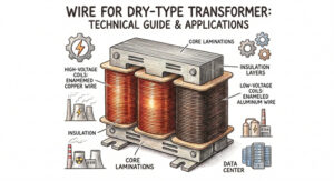
Energy storage boost transformers convert the low-voltage DC power from the battery system into higher-voltage AC power, which is then supplied to the grid or local distribution system. Compared to conventional distribution transformers, energy storage boost transformers operate under significantly different conditions. Energy storage transformers need to withstand frequent load changes and bidirectional power flow. When the battery is charging, electrical energy flows from the grid to the battery, and the transformer operates in the forward direction; when the battery is discharging, electrical energy flows from the battery to the grid, and the transformer operates in the reverse direction. This bidirectional operating mode places higher demands on the insulation structure of the transformer, requiring the insulation material to possess excellent resistance to electrical fatigue and thermal stability. Typical power ratings for energy storage transformers range from hundreds of kVA to tens of MVA. For large-scale energy storage power plants, step-up transformers with rated capacities of 10 MVA to 40 MVA are typically used, and the low-voltage windings, made of rectangular conductors, necessitate glass fiber-coated rectangular conductors.
Technical Advantages of Glass Fiber Coated Wires
Excellent Heat Resistance
The core advantage of glass fiber-coated wires lies in their superior heat resistance. Glass fiber itself has a melting point exceeding 1000 degrees C, maintaining good mechanical strength even under high-temperature conditions. Combined with high-temperature grade insulating varnish treatment, the product can operate stably in high-temperature environments ranging from 180 degrees C to 200 degrees C. The operating temperature range of an energy storage system is typically -20 degrees C to +50 degrees C, and within a sealed containerized energy storage cabinet, the upper temperature limit may reach 70 degrees C to 80 degrees C. The high thermal rating of fiberglass-coated wire provides ample margin for handling such high-temperature conditions, ensuring that insulation performance does not deteriorate under extreme conditions. Thermal aging is a key factor affecting the service life of insulated wires. Insulation materials undergo chemical degradation reactions such as oxidation and thermal decomposition at high temperatures, leading to a gradual decline in insulation performance. Fiberglass-coated wire, with its high thermal rating, effectively reduces the temperature difference between the operating temperature and the rated temperature, extending insulation life.
Reliable Insulation Strength
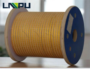
Fiberglass-coated wire employs a composite insulation structure. The primer coating provides basic electrical insulation, the fiberglass braided layer enhances mechanical protection, and the insulating varnish impregnation fills gaps and enhances overall sealing. This composite structure endows the product with excellent dielectric strength and anti-corona performance. Under the high-frequency switching conditions of energy storage converters, the insulation material is subjected to more severe electrical stress than under conventional conditions. Partial discharge is a key factor affecting insulation life; the multi-layered composite structure of fiberglass-coated wire effectively suppresses the generation and development of partial discharge, extending insulation life. The minimum breakdown voltage specified in the standard is an important indicator for evaluating insulation strength. Taking NEMA MW 41-C as an example, the minimum breakdown voltage for a single layer of AWG 4/0 to 9.5 is 170 VAC; for AWG 10 to 23.5 it is 360 VAC; and for AWG 24 to 30 it is 225 VAC. For products with a primer-coated composite insulation structure, the breakdown voltage requirement of the primer layer must be added.
Excellent Mechanical Adaptability
The core and windings of energy storage transformers are subjected to periodic electromagnetic forces during operation. The electrodynamic force generated during a short circuit can be dozens of times that of normal operation, posing a severe test to the mechanical strength of the insulated conductors. The high-strength glass fiber braided layer of the glass fiber coated wire can effectively resist vibration and impact, reducing the risk of insulation layer damage. The glass fiber coated wire also has excellent bending resistance, maintaining insulation integrity at a small bending radius, facilitating the winding of complex coil structures. This feature is of great value for the compact and lightweight design of energy storage devices. Elongation is a key parameter characterizing the mechanical properties of insulated conductors. Taking NEMA MW 41-C as an example, for AWG 4/0 to 1/0, the minimum elongation is 35.0% with and without the fiberglass coating; for AWG 1 to 8, it is 30.0% with and without the coating. A high elongation indicates good toughness and processing adaptability of the conductor.
Good Weather Resistance
The insulating varnish impregnation treatment gives fiberglass-coated wires excellent moisture resistance, dust resistance, and chemical corrosion resistance. This characteristic is of great significance for energy storage applications. Energy storage systems can be used in harsh environments such as outdoor microgrids, offshore wind farms, and desert photovoltaic power stations. The weather resistance of fiberglass-coated wires effectively resists the effects of adverse environmental factors such as wind, sand, salt spray, and humidity, ensuring long-term reliable operation of the equipment. In high humidity environments, moisture absorption by the insulation layer leads to a significant decrease in dielectric strength. The protective layer formed by impregnation with insulating varnish effectively prevents moisture intrusion and maintains long-term stability of insulation performance. For coastal or offshore applications, the salt spray corrosion resistance of fiberglass-coated wires also needs attention.
International Standards and Application Requirements
IEC 60317 Series Standards Requirements
The IEC 60317 series of standards requires that fiberglass-coated wires used in energy storage systems comply with the technical requirements of the IEC 60317 series standards. IEC 60317-48 specifies the technical specifications for 155-grade fiberglass-coated round copper wire; IEC 60317-51 specifies the technical requirements for fiberglass-coated round aluminum wire; IEC 60317-61 specifies the technical requirements for polyester fiberglass-coated rectangular copper wire, applicable to large-capacity energy storage transformers. Key performance indicators specified in the standards include: conductor resistivity, insulation breakdown voltage, bending test, elongation, and thermal aging performance. When purchasing insulated wires, energy storage equipment manufacturers should explicitly require suppliers to provide product qualification certificates and test reports that comply with the corresponding IEC standards. IEC 60317-48 specifies a conductor nominal diameter range of 0.050 mm to 5.00 mm. For large conductors used in energy storage transformers, products with diameters of 1.00 mm to 5.00 mm are typically selected and used in conjunction with rectangular conductors to form transformer windings.
NEMA MW 1000 Standards Requirements
The NEMA MW 1000 standard requires energy storage equipment exported to the North American market to use insulated conductors conforming to the NEMA MW 1000 standard. MW 41-C specifies the technical requirements for 155-grade fiberglass-coated round copper wire, which largely correspond to IEC 60317-48, but differs in testing methods and dimensional systems. The NEMA standard uses the AWG dimensional system, which differs from the IEC metric millimeter system. When selecting conductors, attention should be paid to the accuracy of the conversion to avoid dimensional deviations due to unit confusion. For example, the nominal diameter corresponding to AWG 10 is approximately 2.59 mm, and AWG 8 is approximately 3.26 mm. In addition to MW 41-C, MW 50-C also specifies the technical requirements for 180-grade high-temperature silicone insulating varnish treatment of fiberglass-coated wires. This product has a higher thermal class and is suitable for energy storage devices operating at higher temperatures.
Environmental Compliance
Energy storage devices exported to the European market must meet the requirements of the RoHS Directive and REACH regulations. The insulating varnish, impregnating agents, and other chemical materials of the fiberglass-coated wires must be tested and confirmed to be free of restricted hazardous substances. The RoHS Directive restricts the use of ten categories of hazardous substances, including lead, mercury, cadmium, hexavalent chromium, polybrominated biphenyls, and polybrominated diphenyl ethers. Energy storage device manufacturers should require suppliers of insulated wires to provide RoHS compliance declarations and third-party testing reports. REACH regulations require manufacturers to establish a raw material composition information system for the control of Substances of Very High Concern (SVHCs). Some additives in the insulating varnish may contain substances on the SVHC list, which need to be identified in a timely manner and risk reduction measures should be taken.
Key Considerations for Selection
Thermal Class Matching
The operating temperature environment of the energy storage system is the primary consideration for thermal class selection. The basic principle for selecting the thermal rating is that the rated temperature of the insulated conductor should be 15 degrees C to 20 degrees C higher than the maximum operating temperature of the equipment to allow sufficient thermal aging margin. For energy storage devices installed outdoors or in environments with poor temperature control, products with a high thermal rating of 180 or 200 should be selected to ensure the reliability of the insulation performance under extreme conditions. The internal temperature rise of the energy storage converter is a key parameter for selection. Taking a transformer with a rated temperature rise of 80K as an example, if the ambient temperature is 40 degrees C, the winding temperature can reach 120 degrees C. When selecting a 155-class product (maximum operating temperature 155 degrees C), the temperature rise margin is only 35 degrees C, which is too small; when selecting a 180-class product, the margin can reach 60 degrees C, which is a more reasonable design.
Mechanical Performance Requirements
The winding process and assembly method of the energy storage transformer affect the requirements for the mechanical performance of the insulated conductor. For large transformer windings wound using automatic winding machines, the insulated conductors should possess good flexibility and tensile strength to facilitate control during high-speed winding. The elongation of the fiberglass-coated wire is an important indicator for evaluating its processing adaptability. For example, for NEMA MW 41-C, AWG 4/0 to 1/0 conductors, the minimum elongation with fiberglass coating is 35.0%, and it remains 35.0% after removing the coating. The bending test is an important method for verifying the bond strength between the insulation layer and the conductor. The test involves bending the conductor 180 degrees on a mandrel of a specified diameter and checking for cracking or detachment of the insulation layer. The mandrel diameter is typically 3 to 15 times the nominal diameter of the conductor, with the specific value determined according to the conductor specifications.
Electrical Performance Verification
The electrical performance verification of insulated conductors should include dielectric strength testing and partial discharge testing. Dielectric strength testing verifies the insulation layer’s ability to withstand high voltage without breakdown; partial discharge testing assesses the insulation system’s sensitivity to electric fields. High-frequency switching conditions in energy storage converters may exacerbate partial discharge phenomena. Selecting insulated conductors with low partial discharge characteristics can effectively extend the equipment’s insulation life. Suppliers should provide partial discharge test data or relevant supporting documentation for their products. Insulation resistance testing is a fundamental method for assessing the moisture and contamination levels of the insulation layer. For energy storage equipment stored or operating in humid environments for extended periods, regular monitoring of insulation resistance helps in the timely detection of insulation degradation.
Supplier Qualification Assessment
Energy storage systems have extremely high reliability requirements; equipment manufacturers should establish a rigorous supplier evaluation system. Supplier evaluation should focus on the following aspects: quality management system certification (e.g., ISO 9001), product certification (e.g., UL, VDE), third-party testing reports, production capacity and technical strength, historical quality performance, and customer feedback. On-site audits of key raw material suppliers are recommended to assess their quality control capabilities and continuous improvement mechanisms. The audit content includes: raw material incoming inspection procedures, process quality control points, finished product inspection capabilities, non-conforming product handling procedures, and customer complaint handling mechanisms. If necessary, suppliers may be required to provide sample testing and small-batch trial verification. Testing should cover key indicators such as dimensions, electrical performance, mechanical performance, and heat resistance.
Application Case Analysis
Containerized Energy Storage System
Containerized energy storage systems are currently the mainstream application form of electrochemical energy storage. They integrate battery cabinets, energy storage converters, power distribution systems, and monitoring systems within a standard container, offering advantages such as flexible deployment, short construction cycles, and high mobility. Internal temperature control of the containerized energy storage system is a key technical challenge. The heat generated by the energy storage converter and the step-up transformer needs to be effectively dissipated through a temperature control system; otherwise, excessively high local temperatures will affect the performance of the enameled wires. Using 180-grade or 200-grade high-heat-rating fiberglass-coated wire can provide a greater safety margin for temperature rise design and improve the operational reliability of the equipment in high-temperature environments. Taking a standard 40-foot container as an example, the energy storage capacity of a single container is typically 3 MWh to 5 MWh, configured with a 1 MW to 2 MW energy storage converter. While the demand for insulated wires in the internal transformer and inductor components is not as high as in large-scale energy storage power stations, the reliability requirements are equally stringent.
Mobile Energy Storage Power Supplies
Mobile energy storage power supplies (such as mobile charging vehicles and emergency backup power supplies) need to achieve large-capacity energy storage functions within a relatively compact space. The transformers and inductor components inside the equipment adopt a high power density design, placing higher demands on the performance and dimensional accuracy of the insulated wires. The advantage of using fiberglass-coated wires in high-power-density transformers lies in their excellent heat dissipation performance and reliable insulation strength. The fiberglass layer itself has a porous structure, which is conducive to heat conduction and dissipation; the dense protective layer formed by the insulating varnish impregnation treatment can effectively prevent damage to the insulation layer under vibration and impact loads. Mobile energy storage power supplies may be subjected to vibration and impact loads during transportation and use. The high mechanical strength and excellent vibration resistance of fiberglass-coated wires effectively ensure the reliable operation of equipment under harsh conditions.
Distributed Microgrid Energy Storage
Distributed microgrids are typically installed on the rooftops or underground spaces of industrial and commercial buildings, where ambient temperature fluctuates greatly and humidity is high. The moisture-proof performance of fiberglass-coated wires is crucial for ensuring the reliability of equipment in such application scenarios. The protective layer formed by the impregnation treatment of insulating varnish effectively blocks moisture intrusion, preventing the insulation layer from becoming damp and reducing its electrical strength. In applications in coastal or salt spray environments, the salt spray corrosion resistance of the product must also be considered; reinforced products with special protective treatment can be used if necessary. Distributed energy storage systems have high maintenance costs and strict requirements for equipment reliability. Using energy storage transformers with high-quality insulated wires can effectively reduce the failure rate and decrease maintenance frequency and costs.
Large-Scale Energy Storage Power Stations
Large-scale energy storage power stations are important facilities for realizing grid-side energy storage peak shaving and frequency regulation, with single-station capacities ranging from hundreds of MWh to GWh. Large-scale energy storage power stations have a huge demand for insulated conductors, placing higher demands on suppliers’ production capacity and quality stability. Taking a 100 MW/200 MWh energy storage power station as an example, equipped with a 35 kV step-up transformer, the transformer capacity is typically 50 MVA. The low-voltage side uses rectangular fiberglass-coated conductors, with each transformer requiring several tons of conductors. The entire project has stringent requirements for the quality and supply stability of the insulated conductors. The design life of large-scale energy storage power stations is typically 20 to 25 years, placing even higher demands on the durability of the insulated conductors. Selecting fiberglass-coated conductors that meet international standards and have stable quality is a crucial foundation for ensuring the long-term reliable operation of the power station.
Conclusion
Fiberglass-coated conductors, with their excellent heat resistance, reliable insulation strength, good mechanical adaptability, and weather resistance, have broad application prospects in the energy storage system field. The requirements for insulated conductors in energy storage systems cover multiple dimensions, including thermal rating matching, mechanical properties, electrical performance, and environmental compliance. When selecting energy storage equipment, manufacturers should fully consider the operating characteristics and environmental requirements of the energy storage system, choosing high-quality insulated conductor products that meet relevant standards. Establishing a sound supplier evaluation mechanism is crucial for ensuring supply chain quality stability and product reliability. With the continuous development of the new energy industry and the ongoing advancements in energy storage technology, the application of fiberglass-coated conductors in energy storage systems will become more widespread and in-depth. The demand for high-energy-density, long-life, and high-reliability energy storage equipment will drive continuous innovation and upgrading of insulated conductor technology, providing vital support for building a clean and low-carbon energy system.