
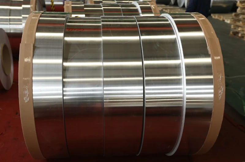
Aluminum foil used for energy storage inductorsis a major conductor material in energy storage inductor winding production. Energy storage inductors are passive electronic components that store energy via magnetic fields generated by coils, which are used in the fields of switching power supplies, frequency conversion drive, renewable energy generation, electric vehicle battery management system, rail transit traction system, welding machine, induction heating and many other fields.
I. Working Characteristics and Principles of Energy Storage Inductors
1.1 Working Principle
The energy storage equation is : W = 1/2 x L x I 2, where W is energy stored, in joules, L is inductance, measured in henries, and I the current, in amperes. The energy stored in the inductor is directly proportional to the value of its inductance, and to the square of the current running through it.
1.2 Operating Characteristics
High current-carrying capacity: Energy storage inductors typically need to carry currents ranging from several amperes to thousands of amperes. In electric vehicle battery management systems, they may need to handle over 100A; in rail transit traction systems, currents can reach thousands of amperes.
High energy storage density: Energy storage inductors need to store large amounts of energy while maintaining relatively compact dimensions, requiring high inductance values and low DC resistance.
Excellent thermal dissipation: Energy storage inductors generate significant heat during high-current operation, requiring effective thermal management designs.
High reliability requirements: Typically need to operate stably for tens of thousands of hours. Requirements are particularly stringent in automotive electronics and industrial applications.
Wide operating frequency range: From DC to dozens of kHz. In switching power supplies, energy storage inductors typically operate in the 20kHz-100kHz range.
1.3 Core Application Areas
Switching power supplies (20-100kHz), electric vehicles (BMS/OBC), renewable energy (PV/wind), rail transit, industrial welding, induction heating, and UPS systems.
II. Special Requirements for Aluminum Foil Materials
2.1 Excellent Electrical Conductivity
Aluminum 1060 has IACS 59-61% conductivity and this level of conductivity provides a basis for most energy storage inductor designs. If a higher power use of the inductor is deemed necessary then a higher conductivity aluminum alloy such as 1070 (IACS 61-62%) could be used.
Low resistivity means less heat generation during operation, improving efficiency and thermal performance. In high-current applications, even small resistance differences lead to significant power losses.
Aluminum’s temperature coefficient of resistivity is approximately +0.4%/°C, meaning resistance increases in high-temperature environments. Temperature rise calculations must be performed to ensure normal operation within rated temperature ranges.
2.2 Excellent Mechanical Properties
Tensile strength: Typically in the 55-125MPa range, depending on alloy state and thickness. High-strength aluminum foil maintains shape stability during winding and tension control.
Appropriate elongation: Annealed aluminum foil typically has elongation ≥25%, allowing it to adapt to complex bending shapes without cracking.
Good flexibility: Particularly important in multi-layer winding structures. Aluminum foil with poor flexibility easily generates micro-cracks during winding, which may expand during long-term use, causing inductor failure.
2.3 Excellent Thermal Resistance
Energy storage inductors generate significant heat under high-current conditions, with aluminum foil temperatures potentially rising above 100°C. Good high-temperature stability maintains mechanical and electrical properties. Aluminum’s natural oxidation film provides some self-protection, though additional corrosion protection may be needed in harsh environments.
2.4 Precise Dimensional Accuracy
Thickness accuracy directly affects turns count and magnetic circuit cross-sectional area, thereby influencing inductance values. Width accuracy affects winding fill factor and electrical performance. Thickness uniformity ensures consistent product performance across batches.
2.5 Excellent Processing Performance
Winding performance: Aluminum foil should smoothly pass through winding equipment without folding, cracking, or breaking.
Welding performance: Foil ends should be easily welded or crimped with low contact resistance.
Fatigue resistance: Winding assemblies must maintain stable performance without cracking under temperature cycling and vibration conditions.
III. Specifications
3.1 Aluminum Foil Substrate Specifications
| Material | Al Content | Conductivity | Characteristics |
|---|---|---|---|
| 1060 | ≥99.60% | IACS 59-61% | Good conductivity, machinability, corrosion resistance |
| 1070 | ≥99.70% | IACS 61-62% | Higher purity and conductivity |
| 3003 | 98.5-99.0% | IACS 42-50% | Higher strength |
| 8011 | ≥98.0% | IACS 45-55% | Good machinability |
3.2 Thickness Range and Selection
| Thickness Range | Current Range | Main Applications |
|---|---|---|
| 0.05-0.1mm | 1-20A | Small power |
| 0.1-0.2mm | 20-50A | Medium power |
| 0.2-0.5mm | 50-200A | Large power |
| 0.5-1.0mm | 200-500A | Extra-large power |
| 1.0-3.0mm | >500A | Industrial grade |
3.3 Mechanical Properties
| State | Tensile Strength | Elongation | Applications |
|---|---|---|---|
| O State (Annealed) | 55-95MPa | ≥25% | Bending and forming |
| H14 State (Semi-hard) | 95-125MPa | ≥10% | Balance of strength and machinability |
| H18 State (Hard) | ≥125MPa | ≥2% | High strength applications |
3.4 Frequency Characteristics
At low frequency (DC-1kHz), skin effect is minimal, and thickness selection is mainly based on current-carrying capacity. At medium frequency (1kHz-20kHz), skin effect should be considered—at 20kHz, skin depth is approximately 0.47mm. At high frequency (>20kHz), skin effect is significant, requiring thinner foil or multi-strand parallel winding structures.
IV. Selection Guide
4.1 Selection by Power Level
| Power Level | Current Range | Thickness | Material | State |
|---|---|---|---|---|
| Small (<1kW) | 1-20A | 0.05-0.15mm | 1060 | O/H14 |
| Medium (1-10kW) | 20-100A | 0.1-0.3mm | 1060/1070 | H14/H18 |
| Large (10-50kW) | 100-300A | 0.3-0.8mm | 1060 | H18 |
| Extra-large (>50kW) | >300A | 0.8-3.0mm | 1060 | H18 |
4.2 Selection by Operating Frequency
- DC-1kHz: Thickness 0.1-3.0mm, H14/H18 state
- 1kHz-20kHz: Thickness 0.05-0.5mm, state depends on power requirements
- >20kHz: Thickness 0.05-0.2mm, multi-strand winding may be required
4.3 Selection by Insulation Class
General insulation: H14 or H18 state, basic insulation treatment
Enhanced insulation: H18 state, H-class insulation coating
Special insulation: Special treatment with enhanced insulation coating or sleeves
V. Dimensional Tolerance Requirements
Thickness tolerance: ±0.02mm (standard) to ±0.005mm (ultra-high precision)
Width tolerance: ±0.3mm (standard) to ±0.05mm (ultra-high precision)
Thickness uniformity: ≤±3% along full roll length; ≤±1% across roll width
VI. Production Process
Raw material preparation → Smelting and casting → Hot rolling → Cold rolling → Annealing → Slitting → Inspection
Key controls: Chemical composition, thickness uniformity ±0.001mm, smooth surface, clean edges
VII. Quality Inspection
- Chemical composition: Spectroscopic analysis
- Dimensional: Thickness gauge (0.001mm accuracy)
- Mechanical properties: Universal testing machine
- Electrical: Eddy current conductivity meter (IACS ≥59% for 1060)
- Appearance: Surface and edge defect inspection
VIII. Supplier Selection
Key points: Material quality, specification range, thickness precision, mechanical property control, testing capability, technical support
Testing process: Dimensional inspection → Appearance inspection → Performance test → Winding test → Finished product test
IX. Common Specifications
| Application | Thickness | Material | Notes |
|---|---|---|---|
| Switching power supplies | 0.1-0.5mm | 1060 | 20-100kHz |
| Electric vehicles | 0.2-1.0mm | 1060/1070 | High reliability |
| Renewable energy | 0.2-0.8mm | 1060 | Medium-high frequency |
| Rail transit | 0.5-3.0mm | 1060 | High current industrial |
| Industrial welding | 0.3-1.0mm | 1060 | High reliability |
X. Conclusion
30 years of experience exporting electrical wire and metal foil. Multiple aluminum alloy materials available: 1060/1070/3003/8011. Thickness range 0.05-3.0mm for all power levels. Multiple states available: O, H14, H18. Ultra-high thickness precision ±0.005mm. Excellent thickness uniformity ≤±3%. Complete test reports for each batch. Customized specifications and selection support available.
Contact:
Email: office@cnlpzz.com
WhatsApp: 0086-19337889070