
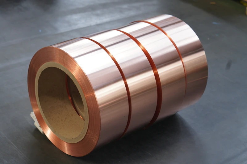
Copper foil for high-power inductors is a key conductive material in the manufacturing of high-power inductor windings. High-power inductors are important passive electronic components that store and release energy through electromagnetic induction, widely used in power conversion, new energy power generation, electric vehicles, rail transportation, industrial control, and other fields.
I. Operating Characteristics of High-Power Inductors
Relative to regular inductors, high power inductors display the following main features: Ability to switch large currents, with the ability to switch from a few amperes to thousands of amperes. Requires high heat dissipation (large current will produce large heat) Complex magnetic circuit design takes into account magnetic saturation and magnetic leakage.
Wide operating frequency range. from DC to a few MHz High reliability requirements, the order of tens of thousands of hours of service life The core functions are: storing and releasing energy, filtering and EMI suppression, power factor correction, conversion of energy and regulation of voltage.
II. Four Requirements for Copper Foil Materials
Firstly, very high conductivity. copper containing up to 99.90%.high conductivity of IACS to 98%, then reduced copper loss,the efficiency of the inverter.
Secondly, the mechanical strength and stiffness are also the important factors for the wound coil transformer. Able to resist the bending stress occurred during winding, and also able to provide the thermal expansion stresses during operating.
Third, good heat resistance. Under high current conditions, temperature of the copper foil may exceed 100degreesC.
Fourth, dependability of dimensional accuracy. The dimensions like width, height are directly related with electrical parameters.
III. Detailed Specifications
3.1 Copper Foil Substrate
- Material: Pure copper C11000, copper content ≥99.90%
- Conductivity: Annealed state IACS ≥98%
- Thickness Range: 0.05-3.0mm
- Width Range: 5-600mm
3.2 Mechanical Properties
O State (Annealed): Tensile strength 200-260MPa, elongation ≥35%
H04 State (Semi-hard): Tensile strength 260-320MPa, elongation ≥20%
H06 State (Hard): Tensile strength ≥320MPa, elongation ≥5%
3.3 High-Frequency Performance Parameters
| Operating Frequency | Skin Depth | Recommended Copper Foil Thickness |
|---|---|---|
| 100Hz | 6.6mm | 0.3-1.0mm |
| 1kHz | 2.1mm | 0.1-0.25mm |
| 10kHz | 0.66mm | 0.05-0.15mm |
| 100kHz | 0.21mm | 0.02-0.08mm |
| 1MHz | 0.066mm | Multi-strand parallel winding |
IV. Selection Guide
4.1 Selection by Current Rating
| Current Rating | Recommended Thickness | Recommended Width | Recommended State |
|---|---|---|---|
| Small Power (<100A) | 0.1-0.3mm | 10-50mm | O-state |
| Medium Power (100-500A) | 0.2-0.5mm | 30-100mm | O-state or H04-state |
| High Power (500-2000A) | 0.3-1.0mm | 50-200mm | H04-state |
| Ultra-High Power (>2000A) | 0.5-3.0mm | 100-600mm | H04-state or H06-state |
4.2 Selection by Operating Frequency
DC or Low Frequency (<1kHz): Ordinary thickness copper foil is sufficient
Medium Frequency (1kHz-10kHz): Consider skin effect, recommend 0.1-0.3mm
High Frequency (10kHz-100kHz): Significant skin effect, recommend 0.05-0.15mm
Ultra-High Frequency (>100kHz): Multi-strand fine copper foil winding
4.3 Selection by Insulation Class
General insulation: O-state annealed copper foil with surface insulation treatment
Higher insulation: H-class insulating coating, heat resistance 180°C
V. Dimensional Tolerance Requirements
Thickness tolerance: Standard ±0.02mm, High precision ±0.01mm, Ultra-high precision ±0.005mm
Width tolerance: Standard ±0.3mm, High precision ±0.1mm, Ultra-high precision ±0.05mm
VI. Key Points of Production Process
6.1 Copper Foil Substrate Production
C11000 electrolytic copper plate → hot rolling → cold rolling → annealing
Key Control Points: Copper content ≥99.90%, strict impurity control, thickness uniformity ±0.01mm, smooth surface, burr-free edges
6.2 Insulation Coating Treatment
- Ordinary insulation: anti-oxidation + basic insulation
- H-class insulation: heat resistance 180°C
6.3 Precision Slitting and Forming
Width tolerance per precision requirements, edges neat and burr-free, length customized
VII. Quality Inspection Methods
7.1 Dimensional Inspection
Thickness: electronic micrometer (0.001mm accuracy); Width: projector/vernier caliper; Length: steel tape measure
7.2 Appearance Inspection
Surface: scratches, indentations, oxide spots; Edge: burrs, rough edges
7.3 Performance Inspection
Mechanical: universal testing machine; Electrical: eddy current conductivity meter (IACS ≥98%)
VIII. Supplier Selection Recommendations
Key points: Material quality (C11000, copper content ≥99.90%), specifications range (0.05-3.0mm thickness, 5-600mm width), high-frequency copper foil supply capability, testing capability
Sample testing: Dimensional inspection → Conductivity test → Mechanical property test → Winding suitability test
IX. Commonly Used Specifications
| Thickness | Width Range | State | Typical Applications |
|---|---|---|---|
| 0.1mm | 10-30mm | O-state | High frequency inductor |
| 0.2mm | 20-60mm | O-state | Medium power inductor |
| 0.3mm | 30-100mm | O-state or H04-state | High power inductor |
| 0.5mm | 50-150mm | H04-state | Ultra-high power inductor |
| 1.0mm | 100-300mm | H04-state | Industrial grade inductor |
| 2.0mm | 200-500mm | H04-state or H06-state | Extra-high power inductor |
X. Conclusion
Our company has 30 years of experience in exporting electrical wire and metal foil, specializing in copper foil for high-power inductors.
Core advantages:
- C11000 pure copper, copper content ≥99.90%, conductivity IACS ≥98%
- Thickness range 0.05-3.0mm, width range 5-600mm
- High-frequency thin-gauge copper foil in regular stock
- Thickness tolerance ±0.01mm, width tolerance ±0.1mm
- Each batch comes with test reports
- Customized specifications available
- Samples shipped globally
Contact our technical team for selection support.
Contact Information:
Email: office@cnlpzz.com
WhatsApp: 0086-19337889070