
Short circuit failures in enameled copper wire represent one of the most common and costly problems in electrical equipment manufacturing and maintenance. Understanding the root causes of these failures is essential for engineers, technicians, and quality professionals who work with motors, transformers, generators, and other electromagnetic devices. Preventing short circuits requires knowledge of both the fundamental mechanisms that cause insulation failure and the practical steps that can prevent these failures from occurring. Enameled copper wire, also known as magnet wire or winding wire, forms the functional core of countless electrical devices.
The thin enamel insulation that distinguishes this wire from ordinary copper conductors enables the tight coil windings necessary for efficient electromagnetic operation. When this insulation fails, the consequences range from degraded performance to complete device failure, and in extreme cases, to fire hazards. This comprehensive guide examines the causes of short circuits in enameled copper wire, explaining the mechanisms behind each failure mode and presenting practical solutions for prevention. The information presented here draws on established principles of materials science, electrical engineering, and manufacturing technology to provide actionable guidance for reducing short circuit failures.
Understanding Enameled Copper Wire and Its Insulation
Construction and Function of Enamel Insulation
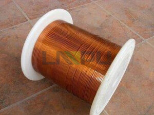
Enameled copper wire consists of a copper conductor coated with a thin layer of electrical insulation specifically formulated for electromagnetic applications. The enamel coating serves as the primary electrical barrier between adjacent turns of wire in a coil, preventing current from flowing anywhere except along the intended conductive path. The enamel coating is typically applied in multiple thin layers, with each layer being individually cured before the next is applied. This multi-coat construction produces a pinhole-free insulation layer that provides reliable electrical isolation even at the minimal thicknesses typical of magnet wire insulation.
A typical magnet wire might have total insulation thickness ranging from 0.02 mm to 0.15 mm depending on the voltage rating and thermal class. The insulating enamel must fulfill multiple simultaneous functions. It must provide high dielectric strength to prevent breakdown under voltage stress. It must adhere firmly to the copper conductor to resist mechanical stresses.
It must remain flexible enough to accommodate winding without cracking. It must withstand elevated temperatures throughout the equipment service life. And it must resist degradation from chemical exposure and environmental factors.
How Short Circuits Occur
A short circuit in enameled copper wire occurs when the enamel insulation fails to prevent electrical contact between the conductor and another conductive surface. In a wound coil, this typically means contact between adjacent turns of wire, creating a low-resistance path that diverts current from its intended path. When a short circuit develops between turns, the affected coil portion becomes effectively bypassed. This changes the electromagnetic characteristics of the device, potentially causing excessive current draw, reduced performance, overheating, and eventual complete failure if the condition persists.
In severe cases, the localized heating from short circuit current can cause visible damage including burned insulation, melted wire, and even fire. The mechanisms that lead to short circuits can be categorized as either manufacturing defects that exist from the start, or degradation failures that develop during service. Understanding this distinction is important for diagnosis and prevention. Manufacturing defects cause early-life failures, often appearing during testing or initial operation.
Degradation failures occur after extended service, resulting from cumulative damage that exceeds the insulation’s capability to withstand operational stresses.
The Importance of Prevention
Preventing short circuits in enameled copper wire is critical for multiple reasons spanning safety, reliability, and economics. The costs of failure extend far beyond the direct repair or replacement expenses. Safety implications represent the most serious concern. Electrical equipment failures involving short circuits can cause fires that threaten lives and property.
In critical applications such as medical equipment, transportation systems, or industrial machinery, equipment failures can have catastrophic consequences. Reliability requirements drive many prevention efforts. Electrical equipment is expected to operate safely for years or decades, often in challenging environments with temperature extremes, humidity, vibration, and chemical exposure. Insulation systems must be designed and manufactured to withstand these conditions throughout the expected service life.
Economic considerations include direct costs of repairs and replacements, but extend to productivity losses from equipment downtime, warranty expenses, and reputational damage. For high-volume equipment manufacturers, even small improvements in failure rates translate to substantial cost savings.
Manufacturing Defects as Causes of Short Circuits
Insufficient Coating Thickness
One of the most fundamental manufacturing defects that can cause short circuits is insufficient enamel coating thickness. When the insulation is too thin, it cannot withstand the voltage stress imposed during operation, leading to premature breakdown. Coating thickness is controlled during the manufacturing process through careful management of application parameters and cure conditions. Variations in coating equipment calibration, raw material properties, or process conditions can result in thin spots or overall insufficient thickness.
Modern manufacturing employs statistical process control and automated inspection to minimize this risk, but some variation is inherent in any process. Quality testing during and after manufacturing detects most thickness problems before wire ships to customers. Dielectric testing applies voltage stress that reveals weak points in the insulation. However, some thin spots may escape detection if they are located where test voltage does not fully stress the area, only to fail later under actual service conditions.
Prevention of thin coating defects requires strict process control, regular equipment maintenance and calibration, and appropriate testing at levels sufficient to reveal marginal quality. Wire users can reduce risk by specifying quality levels appropriate to their application requirements and by working with suppliers who maintain robust quality systems.
Pinholes and Voids
Pinholes are small imperfections in the enamel coating that penetrate through to the copper conductor surface, creating direct paths for electrical breakdown. Voids are internal defects within the coating layer that may not reach the surface but create weak points where breakdown can initiate. Pinholes originate from various causes during manufacturing. Particles or contaminants on the conductor surface can prevent proper enamel adhesion, creating voids that penetrate through the coating.
Bubbles in the liquid enamel coating can cause voids when they burst during application or curing. Inadequate coating coverage at edges, corners, or surface irregularities creates vulnerable points. The multi-coat construction used in quality magnet wire provides protection against pinhole defects. A single thin coating might have pinholes that penetrate directly to the conductor, but successive coats are applied to overlap and seal any such defects in previous layers.
When pinholes in one coat do not align with pinholes in subsequent coats, the composite insulation remains continuous and defect-free. Detection of pinholes and voids requires careful inspection and testing. High-voltage dielectric tests can often detect these defects by causing breakdown at the weak points. However, some pinholes may be too small to detect reliably, only to grow larger over time through gradual degradation or repeated voltage stress.
Contamination and Adhesion Problems
Contamination on the copper conductor surface before enamel application prevents proper adhesion of the insulation to the metal. Poor adhesion creates gaps between the enamel and conductor where moisture or contaminants can penetrate, eventually reaching the conductor surface. Common surface contaminants include drawing lubricants that are not fully removed, oxide films that form on the copper surface, handling residues from fingers or gloves, and airborne particles that settle on the conductor. Quality surface preparation includes chemical cleaning, rinsing, and drying to remove all contaminants before enamel application.
The cleaning process must also avoid creating new contamination or surface conditions that impair adhesion. Chemical cleaning solutions must be completely rinsed away, or residue from the cleaning process itself can become a contaminant. Water used for rinsing must be pure, as dissolved minerals can leave deposits that impair adhesion. Environmental contamination during the coating process presents another risk.
Dust, fibers, and other airborne materials can become embedded in the wet enamel coating or deposited on surfaces before coating. Clean manufacturing environments and careful material handling reduce these risks.
Handling Damage
Mechanical damage to enamel insulation can occur during handling, shipping, or subsequent processing. This damage creates weak points or penetration paths that can lead to short circuits. Physical impacts can crack or chip the enamel coating, particularly in larger wire sizes where the insulation is relatively more brittle. Impacts may occur from dropping wire packages, from contact with sharp objects, or from collisions during handling in automated equipment.
Scratches from abrasive contact can thin or penetrate the enamel coating. Even superficial scratches that do not immediately cause failure can create stress concentrations that lead to eventual breakdown under voltage stress. Scratches may occur from contact with guides, pulleys, or other processing equipment. Crushing or compression damage can occur if wire is wound under excessive tension or if packages are stacked improperly.
The compressive forces can delaminate the enamel from the conductor or crack the coating in ways that may not be immediately visible. Prevention of handling damage requires appropriate packaging, careful material handling procedures, proper equipment maintenance, and appropriate training for everyone who contacts the wire during manufacturing and assembly.
Operational Causes of Short Circuits
Thermal Overload and Degradation
Excess temperature is one of the most common causes of insulation degradation that leads to short circuits during service. All insulation materials have maximum temperature ratings, and operation above these limits accelerates aging processes that progressively degrade electrical and mechanical properties. Thermal degradation of enamel insulation occurs through multiple mechanisms. Oxidation reactions that proceed slowly at normal operating temperatures accelerate at elevated temperatures.
Thermal softening reduces mechanical strength and adhesion. Chemical decomposition of the polymer structure gradually destroys insulating capability. The rate of these degradation processes typically increases exponentially with temperature, meaning that modest overruns can significantly shorten insulation life. Temperature extremes can also cause mechanical damage.
Thermal cycling as equipment heats and cools causes expansion and contraction that stress the insulation. Differential thermal expansion between the copper conductor and the enamel coating creates shear stresses at the interface. If these stresses exceed the adhesive strength, delamination or cracking can result. Overload conditions that cause excess temperature may result from design errors, from equipment being operated beyond its rating, from cooling system failures, or from other faults that increase losses or reduce heat dissipation.
Prevention requires appropriate thermal design, proper equipment selection and application, and maintenance of cooling systems.
Voltage Stress and Dielectric Breakdown
Excessive voltage stress can cause immediate dielectric breakdown of the enamel insulation, creating a conductive path directly through the insulation layer. This can occur from transient overvoltages, from continuous operation at excessively high voltage, or from voltage stress concentration at weak points. Voltage transients such as lightning strikes, switching surges, or fault conditions can impose voltage levels far exceeding normal operating voltage. If these transients exceed the insulation voltage withstand capability, breakdown occurs.
Equipment must be designed and protected to limit transient voltages to levels the insulation can safely withstand. Continuous overvoltage operation, even if not sufficient to cause immediate breakdown, accelerates insulation aging. The mechanisms of dielectric degradation proceed faster at higher voltage stress levels. Operating voltage should be maintained within specified limits to ensure expected insulation life.
Voltage stress concentration at defects or irregularities increases the effective stress on the insulation. A thin spot or void that might withstand normal voltage stress may fail when stress is concentrated at its location. Good manufacturing quality and appropriate testing help ensure that such stress concentrations do not exist in the delivered wire.
Mechanical Stress and Vibration
Repeated mechanical stress from vibration, thermal cycling, or other sources can progressively damage enamel insulation until a short circuit develops. This type of failure often occurs after extended service following cumulative damage. Vibration fatigue is a common cause of mechanical degradation in applications such as motors in pumps, compressors, and transportation equipment. The repeated cyclic stresses from vibration can cause cracking or delamination of the enamel coating, particularly if the wire is under tension or if resonance conditions amplify the stress levels.
Thermal cycling causes repeated expansion and contraction of both conductor and insulation. The copper conductor and the enamel coating have different coefficients of thermal expansion, creating cyclic shear stresses at their interface. Over many cycles, these stresses can cause progressive delamination or cracking, particularly if the extremes of temperature are severe. Physical movement of the wire in service, such as from magnetic forces during operation or from external mechanical disturbances, can cause abrasion between adjacent turns or against other surfaces.
This abrasion gradually thins the insulation until breakdown occurs. Proper winding tension, appropriate bracing, and vibration damping help prevent this type of damage.
Chemical Attack and Environmental Degradation
Exposure to chemicals or environmental factors can degrade enamel insulation over time, eventually leading to short circuit failure. Different enamel systems have varying resistance to different environmental factors, and proper material selection is essential. Transformer oils and other insulating liquids used in some equipment can affect enamel insulation. While modern magnet wire enamels are formulated for compatibility with common refrigerants and oils, some combinations may cause gradual degradation, particularly at elevated temperatures.
Material compatibility should be verified for the specific fluids involved. Moisture penetration into the winding over time can cause various degradation mechanisms. Hydrolysis of the enamel polymer reduces molecular weight and mechanical strength. Galvanic corrosion of the copper conductor under voltage stress can create conductive paths.
Moisture-accelerated failures are particularly common in applications with high humidity exposure or where condensation can occur. Chemicals in the operating environment can attack enamel insulation. Cleaning solvents, industrial chemicals, and even some materials used in manufacturing processes can cause enamel degradation. Appropriate wire selection for the expected chemical exposure conditions is essential.
Application and Design Related Causes
Improper Winding Tension
Excessive winding tension during coil manufacturing can damage enamel insulation, either immediately or through stress that leads to later failure. The tension must be controlled appropriately for the wire size, insulation class, and winding configuration. Too much tension can stretch the conductor and enamel coating, causing thinning of the insulation or cracking. The stress may not cause immediate failure, but creates residual stress concentrations that make the insulation more susceptible to damage from subsequent thermal cycling or voltage stress.
Insufficient tension can result in loose windings that shift during handling or operation. Loose turns can abrade against each other or against the core or housing, gradually wearing through the insulation. Proper winding tension ensures that turns are packed tightly together without excessive stress. Tension variation during winding can cause inconsistent coil properties and stress points.
Automated winding equipment with tension control provides more consistent results than manual winding, though both methods can produce acceptable results with appropriate controls.
Sharp Edges and Bending Radius
Winding over sharp edges or bending the wire too sharply can cause immediate insulation damage or residual stress that leads to later failure. The wire must be bent smoothly around corners and across edges. Core slot edges, tooth tips, and other geometric features in the motor or transformer structure can damage wire if not properly finished. Sharp edges concentrate stress on the insulation, potentially causing cracking or penetration.
Quality cores have edges that are chamfered, rounded, or covered with insulation to protect the wire. The minimum bend radius for magnet wire depends on the wire size, insulation thickness, and the specific enamel system. Bending more sharply than the wire can accommodate causes visible cold working of the conductor and may cause cracking of the enamel coating at the outer surface where strain is greatest. Forced winding around forms or through guides can create stress concentrations if the geometry is not properly designed.
Careful attention to routing paths, guide radii, and former contours helps prevent this type of damage.
Electrical Design Issues
Electrical design choices can create conditions that stress the insulation beyond its capability, leading to premature failure. Proper design accounts for the insulation properties and application conditions. Voltage stress distribution in the winding should be analyzed to ensure that no location experiences stress exceeding the insulation capability. Turn-to-turn voltage stress depends on the voltage difference between adjacent turns, which depends on the voltage gradient across the coil.
In some coil configurations, certain turns may experience higher stress than others. Partial discharge activity can degrade insulation over time, particularly at operating voltages approaching the insulation rating. Partial discharges are small electrical breakdowns that occur in voids or at surface irregularities. While quality enamel insulation has good partial discharge resistance, avoiding designs that operate near the partial discharge inception voltage helps ensure long life.
Surge voltages from switching or fault conditions impose short-duration overvoltages that stress the insulation. Motor windings are particularly susceptible because the switching of power electronics or across-the-line starting creates steep voltage transients. Design for appropriate surge voltage withstand capability is important.
Thermal Design Issues
Inadequate thermal design results in operating temperatures that exceed the insulation rating, accelerating aging and leading to premature failure. The thermal environment of the winding must be properly analyzed and managed. Heat generated within the winding from copper losses and core losses must be conducted away to the cooling medium. If the thermal resistance path is too high, temperatures rise excessively.
Design factors include conductor size, fill factor, core geometry, and cooling provisions. Ambient temperature affects the temperature rise from internal heating. Equipment specified for high ambient conditions may require insulation with higher thermal ratings or more robust cooling provisions. Operating equipment in conditions more severe than those for which it was designed leads to excessive temperature.
Cooling system failures, reduced air flow, clogged filters, or other conditions that impair heat removal cause temperatures to rise. Monitoring and maintenance of cooling systems helps prevent temperature-related failures.
Solutions and Prevention Strategies
Quality Wire Selection
Selecting appropriate quality wire for the application is the first line of defense against short circuit failures. The wire must meet or exceed the requirements of the application in thermal class, voltage rating, and mechanical properties. Specifying appropriate thermal class ensures that the wire rating exceeds the expected operating temperature with adequate margin. Operating at temperatures well below the rating provides margin for unexpected temperature excursions and extends expected life.
Voltage rating should be appropriate for the application with adequate margin for transient overvoltages. Specifying wire with higher voltage rating than strictly required provides additional safety margin. Mechanical property requirements should match the winding process and application conditions. Flexibility requirements, adhesion characteristics, and scrape resistance should be appropriate for the specific manufacturing process and service conditions.
Working with quality suppliers who maintain robust quality systems and can provide technical support helps ensure appropriate wire selection. Material certifications and traceability support quality assurance requirements.
Proper Handling and Storage
Proper handling and storage procedures protect the wire from damage that could lead to short circuits during manufacturing and subsequent service. Everyone who handles wire should understand and follow appropriate procedures. Storage conditions should protect the wire from moisture, chemical exposure, dust, and other environmental factors that could degrade insulation before or during use. Original packaging should be maintained until the wire is needed.
Handling procedures should prevent physical damage from impacts, crushing, or excessive bending. Wire should not be pulled across sharp surfaces, dropped, or subjected to forces beyond its capability. First-in first-out inventory rotation ensures that older stock is used first, minimizing the time wire spends in storage. Wire properties can change over extended storage, and older stock may need verification testing before use.
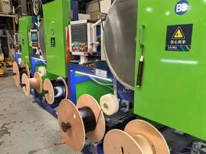
Optimized Winding Processes
Optimized winding processes minimize the risk of insulation damage during coil manufacturing. Process parameters should be established and controlled to protect the wire while achieving efficient production. Winding tension should be set appropriately for the wire size and type. Tension that is too high risks damaging the wire, while tension that is too low results in loose windings.
The optimal tension provides secure positioning without excessive stress. Guide and former geometry should be designed to avoid sharp bends and edges that could damage the wire. Guide surfaces should be smooth and free from burrs or defects that could scratch or catch the insulation. Winding speed should be appropriate for the wire size and complexity of the winding.
High speeds increase productivity but may cause problems if they exceed the wire’s capability or create excessive tension variations. Equipment maintenance ensures consistent process performance. Worn guides, damaged tooling, and misaligned components can damage wire and should be repaired or replaced promptly.
Testing and Quality Assurance
Comprehensive testing and quality assurance programs detect defects and verify that wire and coils meet requirements. Testing at multiple stages helps prevent defective material from progressing through manufacturing. Incoming inspection verifies that received wire meets specifications. Sampling plans appropriate to the risk level and usage volume should be established.
Critical applications may warrant 100% testing. In-process testing during winding can detect problems before they become complete failures. Testing options include continuity checks, high-potential testing, and resistance measurement. Final testing on completed coils or equipment verifies that all manufacturing steps have been completed successfully.
This testing should simulate service conditions to the extent practical and verify that the product meets all performance requirements.
Troubleshooting and Diagnosis
Identifying Short Circuit Failures
Identifying that a short circuit has occurred is typically straightforward through electrical testing or operational symptoms. Determining the specific location and nature of the short may require additional diagnostic effort. Electrical testing reveals the presence and approximate location of shorts. Continuity testing between coil terminations and ground can indicate whether a short to ground exists.
Resistance or inductance measurement between terminals can indicate shorted turns. Visual inspection of accessible windings may reveal the failure location if damage is severe. Burn marks, melted insulation, or other visible damage often point to the failure location. However, not all failures produce visible damage, particularly in hermetically sealed equipment.
Operational symptoms often indicate the type and location of the problem. Excessive current draw, reduced output, overheating, or abnormal noise can provide clues about the failure mechanism.
Root Cause Analysis
Determining the root cause of a short circuit failure is essential for preventing recurrence. A systematic approach considers manufacturing defects, design issues, application conditions, and other factors that could have contributed to the failure. Failure analysis techniques include visual examination, microscopy of the failure site, chemical analysis of degradation products, and mechanical testing of remaining insulation. These techniques can reveal whether the failure was from a manufacturing defect, from operational abuse, or from gradual degradation.
Review of manufacturing records, process parameters, and test results can identify whether a manufacturing defect was present from the start or whether the wire met specifications when shipped. Analysis of operating conditions, maintenance records, and equipment history helps determine whether the failure resulted from application conditions exceeding design assumptions or from abnormal events during service.
Corrective Action Implementation
Implementing corrective actions based on root cause analysis prevents recurrence of similar failures. Actions may be directed at design, manufacturing, purchasing, or application areas. Design changes may be needed if the original design did not adequately account for actual service conditions or stress levels. Such changes might include selecting higher-rated wire, modifying the winding configuration, improving voltage surge protection, or enhancing cooling provisions.
Manufacturing process improvements may be needed if the analysis reveals that manufacturing conditions contributed to the failure. Such improvements might include tightening process controls, improving equipment maintenance, or enhancing testing procedures. Supplier corrective actions may be needed if the wire was defective. Working with suppliers to communicate requirements clearly and resolve quality issues supports long-term quality improvement.
Short circuit failures in enameled copper wire result from a complex interplay of manufacturing defects, design factors, application conditions, and material properties. Understanding the mechanisms that cause these failures provides the foundation for effective prevention. Manufacturing defects including thin coating, pinholes, contamination, and handling damage create vulnerabilities that may cause immediate failure or reduce the insulation’s ability to withstand subsequent service stress. Preventing these defects requires strict process control, appropriate testing, and proper handling throughout manufacturing and assembly.
Operational causes including thermal overload, voltage stress, mechanical stress, and environmental degradation attack the insulation during service, causing gradual degradation that eventually leads to failure. Preventing operational failures requires appropriate design margins, proper equipment application, and maintenance of conditions within design limits. Application and design factors including winding tension, bend radius, electrical stress distribution, and thermal management directly influence insulation stress levels and service life. Optimizing these factors during design and manufacturing reduces the risk of failure.
Prevention of short circuits requires attention throughout the product lifecycle, from wire selection and design through manufacturing, assembly, and service. The investment in prevention pays returns through improved reliability, reduced costs, and enhanced safety.
—
*Keywords: Enameled Copper Wire, Short Circuit, Causes, Solutions, Prevention, Insulation Failure, Magnet Wire, Troubleshooting, Electrical Fault, Motor Winding, Transformer*