
Electric vehicle charging infrastructure is a crucial link in the new energy vehicle industry chain. With the rapid growth of the electric vehicle market, higher requirements are being placed on the efficiency, power density, and reliability of charging equipment. As the core equipment connecting the power grid and the vehicle’s power battery, the design and material selection of the internal transformer of the EV charger directly affect charging efficiency and system stability. In the manufacturing of the charger transformer, copper foil, as an important conductive material, has become the mainstream choice for EV charger transformer windings due to its excellent electrical performance, heat dissipation characteristics, and machinability.
This article will systematically analyze the application of copper foil in EV charger transformers from multiple dimensions, including technical principles, material properties, design points, process challenges, and selection recommendations.
Overview of Electric Vehicle Charger Transformers
Core Functions of Charger Transformers
Charger Transformers An electric vehicle charger is essentially a power conversion device. Its core function is to convert AC grid power into DC power and charge the power battery with appropriate current and voltage according to the requirements of the battery management system. The transformer plays a crucial role in this energy conversion process. Structurally, electric vehicle chargers are mainly divided into two categories: on-board chargers (OBC) and external charging stations.
On-board chargers are integrated inside the vehicle, typically with power levels ranging from 6.6kW to 22kW, requiring efficient energy conversion within a limited volume. External charging stations include AC charging stations (typically 3.3kW to 22kW) and DC fast charging stations (typically 50kW to 350kW or even higher). The transformer inside the charger mainly performs the following functions: voltage conversion (converting the input voltage to a voltage level suitable for rectification), electrical isolation (electrically isolating the grid side from the vehicle side), and power transmission (achieving efficient energy transfer at switching frequencies).
Technical Requirements for Charger Transformers
Transformers Electric vehicle chargers (transformers) need to maintain high performance in harsh operating environments. Their technical requirements mainly include the following aspects: In terms of efficiency, the efficiency of the charger transformer directly affects energy loss during the charging process. High efficiency means lower heat generation, higher power density, and faster charging speed. Currently, mainstream products typically require efficiency above 95%, while high-end products can reach above 98%.
In terms of power density, limited by vehicle space or charging station volume, the transformer needs to maximize power transmission capacity within a given volume. Improving power density relies on improved magnetic material performance, optimized heat dissipation design, and improved winding structure. In terms of heat dissipation, the heat generated during charger operation must be effectively dissipated; otherwise, it will lead to increased temperature, decreased efficiency, and even reduced reliability. The transformer is one of the main heat sources inside the charger, making its heat dissipation design crucial.
In terms of electromagnetic compatibility, as a power electronic device, the charger needs to meet stringent electromagnetic interference (EMI) standards. The transformer design needs to consider parameters such as leakage inductance and distributed capacitance to reduce electromagnetic radiation. In terms of reliability, chargers are typically designed for a lifespan of over 10 years, and the reliability of the transformer directly determines its lifespan.
Technical Characteristics of Copper Foil Material
Basic Physical Properties of Copper Foil
Copper Foil Copper is a metallic material with excellent electrical conductivity, making it an ideal material choice for transformer windings. Regarding conductivity, pure copper has a conductivity of 100% under IACS standards, the highest among all non-precious metals. The resistivity of pure copper is approximately 1.72 × 10⁻⁸ Ω·m (20°C), a value that makes copper the preferred material for transformer windings. Under the same cross-sectional area conditions, copper’s resistance is significantly lower than that of alternative materials such as aluminum.
In terms of thermal properties, copper’s thermal conductivity is approximately 401 W/(m·K), second only to silver among metallic materials. This excellent thermal conductivity allows copper foil windings to effectively dissipate the heat generated during operation, reducing temperature rise. The coefficient of thermal expansion of copper is approximately 17.5 × 10⁻⁶/°C, a parameter that needs to be considered in the design to match the thermal expansion of the insulating material. In terms of mechanical properties, copper has a density of approximately 8.9 g/cm³ and a tensile strength ranging from 200 MPa to 400 MPa (depending on the annealing state and alloy composition).
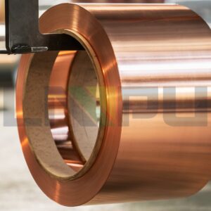
Copper has good ductility and machinability, and can be processed into various copper foil products through rolling, calendering, and other processes.
Technical Advantages of Copper Foil Compared to Other Materials
Copper Foil Compared to Other Materials In the selection of transformer winding materials, copper foil has significant technical advantages compared to aluminum foil and other materials. In terms of conductivity, copper’s conductivity is approximately 1.64 times that of aluminum. This means that under the same current carrying capacity requirements, the cross-sectional area of copper windings can be significantly smaller than that of aluminum windings, thus achieving a more compact volume design. In terms of heat dissipation, copper’s thermal conductivity is approximately 1.69 times that of aluminum.
A higher thermal conductivity means that heat can be conducted more quickly from the inside of the winding to the heat sink, which is especially important for high-power-density chargers. In terms of mechanical strength, copper has higher tensile strength and hardness than aluminum, giving copper foil windings better structural stability under vibration, meeting the vibration standards of the automotive industry. Regarding weldability, copper welding processes are more mature and reliable than aluminum welding. Copper can achieve high-quality connections through various methods such as TIG welding, laser welding, and resistance welding, resulting in low joint resistance and high mechanical strength.
Copper Foil Specifications and Classification
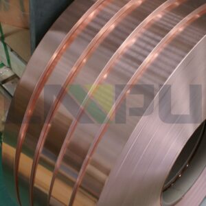
Copper foil used in chargers can be classified according to thickness, width, purity, and processing condition. In terms of thickness, common copper foil thicknesses range from 0.05 mm to 3.0 mm. Thinner copper foil (0.05 mm to 0.3 mm) is mainly used in high-frequency switching power supplies, while thicker copper foil (0.3 mm to 3.0 mm) is used in high-power mains frequency or medium-frequency power supplies. Regarding width specifications, the width of copper foil can be customized according to customer requirements, with common widths ranging from 10 mm to 300 mm.
Wider copper foil can reduce the number of parallel turns in the winding and lower contact resistance. In terms of purity, copper foil used in transformers typically requires a purity of 99.9% or higher. High-purity copper can reduce resistance increases and heat loss caused by impurities. Regarding processing conditions, copper foil can be divided into different states such as soft (R220), semi-hard (R240), and hard (R280).
Soft copper foil is easy to bend and is suitable for winding complex shapes; hard copper foil has higher mechanical strength and is suitable for applications requiring high structural stability.
Design Application of Copper Foil in Charger Transformers
Winding Structure Design
Design The design of copper foil windings in charger transformers needs to comprehensively consider the requirements of electrical performance, heat dissipation performance, and mechanical structure. In terms of winding form, layered windings and foil windings are two main structural forms. Layered windings use copper round wire or flat wire wound layer by layer, resulting in a simple structure and mature technology. Foil windings use copper foil as the conductor, with alternating layers of insulation material in the thickness direction, forming a “sandwich”-like structure.
The advantages of foil windings are: the current conduction direction is parallel to the heat dissipation surface, resulting in good heat dissipation; the winding and insulation layer are integrated, providing high mechanical strength; and multi-layer parallel connection can be achieved, reducing AC resistance. Regarding conductor size design, the thickness of the copper foil needs to consider the skin effect. Under high-frequency application conditions, current tends to flow on the conductor surface, reducing the effective conductive cross-sectional area. It is generally recommended that the copper foil thickness not exceed twice the skin depth.
For switching frequencies from 50 kHz to 100 kHz, the skin depth is approximately 0.3 mm, therefore the copper foil thickness is typically chosen to be 0.1 mm to 0.3 mm. In terms of insulation design, copper foil windings require high-performance insulation materials for interlayer and phase-to-phase insulation. Commonly used insulation materials include: polyester film (PET), polyimide film (PI), NOMEX paper, and Denison paper. The choice of insulation thickness must meet electrical strength requirements while considering the design of heat dissipation channels.
Key Design Considerations for High-Frequency Transformers
The high-frequency transformer in an electric vehicle charger is the core component for power conversion, and its design directly affects charging efficiency and power density. Regarding core selection, high-frequency charger transformers typically use ferrite cores or nanocrystalline cores. Ferrite cores have high resistivity and low high-frequency losses, making them suitable for application frequencies from 20 kHz to 100 kHz. Nanocrystalline cores have higher saturation flux density and better temperature stability, making them suitable for higher frequency or higher power applications.
Regarding the window fill factor, the window fill factor of the copper foil winding is a key parameter affecting power density. The window fill factor is defined as the ratio of the winding conductor cross-sectional area to the core window area. By optimizing the copper foil size and winding process, a fill factor of 0.4 to 0.6 can be achieved, thereby enabling higher power transfer within a given volume. Regarding leakage inductance control, leakage inductance is an important parameter affecting charger efficiency and safety.
Excessive leakage inductance can lead to voltage spikes and electromagnetic interference problems. During the design phase, it is necessary to rationally arrange the winding positions and employ techniques such as segmented windings or shielded windings to control leakage inductance.
Heat Dissipation Design
Dissipation Design The heat dissipation design of the charger’s transformer is a crucial aspect ensuring its reliable operation. Regarding the heat conduction path, heat is generated from the copper windings, conducted through the insulation layer to the magnetic core, and then from the magnetic core to the heat sink or housing. Optimizing the heat conduction path and reducing thermal resistance are the main goals of heat dissipation design. Copper foil windings, due to their close contact with the insulation layer, have good thermal conductivity.
Common heat dissipation methods include natural cooling, forced air cooling, and liquid cooling. For chargers with high power density requirements, forced air cooling or liquid cooling is typically used. Sufficient heat dissipation channels must be reserved during the design phase to ensure that the cooling medium can effectively flow through the transformer. Regarding temperature rise control, the temperature rise of the transformer directly affects its lifespan and efficiency.
The design phase must ensure that, under rated load conditions, the temperature rise is controlled within the thermal class range of the insulation material. For Class F insulation (155°C), the temperature rise is typically required to be no more than 80°C to 100°C.
Key Performance Indicators and Quality Requirements
Technical Specifications of Copper Foil Materials
Copper Foil Materials Copper foil used in electric vehicle chargers (transformers) needs to meet stringent technical specifications. In terms of chemical composition, copper foil for transformers typically uses electrolytic copper (ETP copper) or oxygen-free copper (OFE copper). Electrolytic copper requires a purity of 99.9% or higher, while oxygen-free copper can reach 99.99%. The content of impurity elements (such as iron, sulfur, phosphorus, etc.) needs to be strictly controlled, as these elements reduce conductivity and processing performance.
Regarding dimensional tolerances, thickness tolerance is typically required to be controlled within ±0.01 mm to ±0.05 mm, depending on the thickness grade. Width tolerance is typically required to be controlled within ±0.1 mm to ±0.5 mm. Strict dimensional tolerances are fundamental to ensuring the consistency of winding electrical performance. In terms of mechanical properties, tensile strength needs to be selected according to application requirements.
For windings requiring bending, soft copper foil (tensile strength 200 MPa to 300 MPa, elongation greater than 30%) is usually selected. For applications requiring high mechanical strength, semi-hard or hard copper foil can be selected. Regarding surface quality, the copper foil surface should be clean, flat, free of cracks, peeling, and oxidation discoloration. Surface roughness Ra is typically required to be below 0.8 μm.
Edges should be neat and burr-free. For copper foil requiring welding, the surface should be free of contaminants that affect welding quality.
Quality Control of Winding Manufacturing
Winding Manufacturing The manufacturing quality of copper foil windings directly determines the final performance and reliability of the transformer. In terms of winding process, controlling the winding tension is crucial. Excessive tension may cause copper foil deformation and insulation damage; insufficient tension may cause the winding to become loose and the fill factor reduced. Constant tension winding technology and precise position control are key to ensuring winding quality.
In terms of insulation treatment, the interlayer insulation of the winding needs to be uniform, continuous, and free of bubbles. The insulating paper or film must be tightly wrapped around the copper foil surface to avoid air gaps. For high-voltage applications, multi-layer insulation or reinforced insulation structures may be required. Regarding welding processes, copper welding is relatively mature.
Common welding methods include TIG welding, laser welding, and resistance spot welding. The resistance of the weld joint should be as low as possible, typically requiring a contact resistance less than that of a conductor of the same length. Weld quality needs to be verified through visual inspection, tensile testing, and electrical testing.
Testing and Verification Requirements
Verification Requirements Before being put into use, copper foil windings (transformers) require comprehensive testing and verification. For electrical performance testing, the following tests are required: open-circuit test (verifying turns ratio and no-load loss); short-circuit test (verifying impedance parameters and load loss); insulation resistance test (verifying insulation condition); withstand voltage test (verifying electrical strength, typically requiring AC 2 kV or higher for 1 minute without breakdown); high-frequency impedance characteristic test (for high-frequency transformers). For thermal performance testing, a temperature rise test is required, where the windings and core are measured under rated power conditions until thermal stability is achieved. Thermal cycling tests verify the impact of temperature changes on winding reliability.
For mechanical performance testing, vibration tests are required to verify the structural integrity of the winding under vibration. Vibration tests typically need to meet the requirements of relevant automotive standards such as ISO 16750-3. For environmental adaptability testing, high-temperature, low-temperature, temperature cycling, and damp-heat environmental tests are required to verify the performance stability of the transformer under various environmental conditions.
Process Challenges and Solutions
Skin Effect and Proximity Effect
Proximity Effect Under high-frequency application conditions, the current distribution in the conductor exhibits skin and proximity effects, leading to increased AC resistance and losses. The skin effect refers to the tendency of high-frequency current to flow on the conductor surface, reducing the effective conductive cross-sectional area. The formula for calculating the skin depth δ is: δ = √(2/ωμσ), where ω is the angular frequency, μ is the permeability, and σ is the conductivity. Taking 50 kHz as an example, the skin depth of copper is approximately 0.3 mm.
Therefore, the copper foil thickness used at this frequency is typically no more than 0.6 mm (twice the skin depth). The proximity effect refers to the phenomenon of uneven current distribution caused by the interaction of electromagnetic fields between adjacent conductors. The proximity effect is particularly significant in multilayer windings. To reduce the impact of the proximity effect, the following measures can be taken: layered winding arrangement to reduce interlayer electromagnetic coupling; use thinner and wider copper foil to increase the proportion of conductor width; optimize the winding arrangement sequence to ensure that the current direction of adjacent layers is consistent.
Heat Dissipation and Temperature Rise Control
Dissipation and Temperature Rise Control The heat dissipation design of the high-power-density charger transformer is a technical challenge. In terms of thermal resistance analysis, the internal thermal resistance of the transformer mainly includes: the thermal resistance from the winding to the core, the thermal resistance inside the core, and the thermal resistance from the core to the heat sink. By optimizing the selection and thickness design of the insulating material, the thermal resistance from the winding to the core can be reduced. Using insulating materials with high thermal conductivity (such as thermally conductive silicone rubber) can effectively improve heat dissipation.
In terms of heat dissipation structure, the following measures can be taken: increase heat dissipation channels to ensure that the cooling medium can flow sufficiently through the transformer; use enhanced heat dissipation structures such as Pin-Fin to increase the heat dissipation area; coat the copper foil surface with thermally conductive material to improve contact thermal resistance.
Insulation Aging and Life Prediction
Aging and Lifespan Prediction Under long-term high-temperature operating conditions, the insulation material of the transformer will age, leading to a decrease in insulation performance. The main mechanisms of insulation aging include: thermal aging (high temperature causes the molecular chains of the insulation material to break), oxidative aging (oxygen reacts with the insulation material), and mechanical aging (temperature cycling leads to material fatigue). The lifespan of insulation materials generally follows the Arrhenius equation; for every 10°C increase in temperature, the lifespan is reduced by about half. To extend the transformer’s lifespan, the following measures can be taken: select insulation materials with high temperature resistance; reserve sufficient temperature margin in the design; avoid operating the transformer under full load conditions for a long time; implement temperature monitoring to detect abnormal temperature rises in a timely manner.
Vibration Reliability
Reliability The on-board charger transformer needs to withstand vibration and impact during vehicle operation. Vibration may cause winding loosening, insulation damage, or even open circuit failure. To improve vibration reliability, the following measures can be taken: adopt a foil winding structure, where the copper foil and insulation material are tightly bonded, resulting in high mechanical strength; perform impregnation treatment after winding to solidify the winding and frame into a whole; and use a vibration-resistant fixed structure.
Selection Recommendations and Industry Outlook
Key Points for Copper Foil Transformer Selection When selecting a copper foil charger transformer, it is recommended to focus on the following aspects: Regarding material certification, the copper foil material should have complete material certification documents, including parameters such as chemical composition, mechanical properties, and conductivity. It is recommended to choose a supplier that can provide third-party testing reports. Regarding design capabilities, the transformer manufacturer should have complete design capabilities, including core selection, winding design, heat dissipation design, and process verification. It is recommended to review their design cases and simulation capabilities.
Regarding manufacturing processes, the maturity and quality control level of the winding manufacturing process directly affect product consistency. It is recommended to examine the supplier’s production equipment, testing equipment, and process documents. Regarding certifications, the product should have passed necessary certifications, such as UL certification and CE certification. For automotive applications, IATF 16949 certification is a basic requirement for suppliers to enter the automotive supply chain.
Industry Development Trends
Development Trends The copper foil charger (transformer) field is showing the following development trends: In terms of power enhancement, with the rapid development of fast charging technology for electric vehicles, charger power levels continue to increase. 400V platform models generally support fast charging above 150 kW, while 800V platform models support 350 kW or even higher power. Increased power places higher demands on the power density and heat dissipation performance of the transformer. In terms of efficiency enhancement, energy loss during charging is directly converted into heat; high efficiency means lower heat dissipation requirements and higher charging efficiency. The application of new wide-bandgap semiconductor devices (SiC, GaN) enables charger efficiency to reach 97% to 98% or higher.
In terms of integration, the design of OBC and DC-DC integrated units is becoming increasingly common. Integrated design places higher demands on the size and performance of magnetic components, driving the continuous progress of copper foil (transformer) technology. In terms of standardization, to reduce development costs and accelerate product launch time, OEMs are increasingly inclined to adopt platform-based design approaches. The standardization and modular design of transformer has become the development direction of the industry.
Technological Innovation Directions
The technological innovation of copper foil charger transformer mainly focuses on the following directions: In terms of material innovation, the development of new copper alloy materials (such as copper-silver alloy and copper-tin alloy) can improve mechanical properties while maintaining high conductivity. The development of ultra-fine grain copper foil materials can improve high-frequency performance. In terms of process innovation, the application of new winding technologies (such as automatic winding technology and laser welding technology) can improve production efficiency and product quality. The application of vacuum impregnation technology can improve the heat dissipation performance and mechanical strength of the winding.
In terms of design innovation, the application of finite element analysis (FEA) technology makes transformer design more refined and more reliable. Thermal-structural-electromagnetic multiphysics coupling simulation has become an important tool for transformer optimization design.
![]()
As the core material of electric vehicle charger transformer, copper foil occupies a dominant position in the charger transformer field due to its excellent conductivity, heat dissipation performance and machinability. From a technical perspective, copper foil exhibits significantly superior electrical and thermal conductivity compared to alternative materials like aluminum, making it crucial for achieving high-efficiency, high-power-density chargers. The design of copper foil windings requires comprehensive consideration of factors such as the skin effect, proximity effect, heat dissipation design, and vibration reliability. From a reliability perspective, through appropriate material selection, structural design, and process control, copper foil windings can meet the stringent reliability requirements of electric vehicle chargers.
The selection of insulation materials and temperature rise control are key to ensuring long-term reliability. From an industry development perspective, with the rapid development of fast-charging technology for electric vehicles and the continuous improvement of power levels, copper foil chargers face higher technical requirements and a larger market space. The application of new materials, new processes, and new designs will drive technological progress and industrial upgrading in copper foil chargers. In summary, the application of copper foil in electric vehicle chargers is a result of a combination of technical feasibility, market demand, and reliability requirements.
For electric vehicle charger manufacturers pursuing high efficiency, high power density, and high reliability, copper foil windings are an irreplaceable technological choice.