
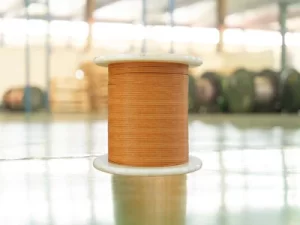
This article systematically elaborates on the structural composition of fiberglass covered wire for sale from the aspects of conductor materials, fiberglass insulation layer, impregnating insulating varnish, and composite structural characteristics, and deeply analyzes the material characteristics, process requirements, and their impact on final product performance of each component.
1. Conductor Materials
1.1 Copper Conductors
Copper is the most commonly used conductor material for fiberglass covered wire, with the following advantages:
High Conductivity: Copper has a conductivity of approximately 58 S·m/mm² (100% IACS), second only to silver among all metal conductors. High conductivity means lower DC resistance under the same cross-sectional area, resulting in lower copper loss during motor or transformer operation and higher efficiency.
Excellent Mechanical Properties: Copper has good ductility and tensile strength, with tensile strength typically between 200~250 MPa, capable of withstanding mechanical stress during drawing, winding, embedding, and other processing operations.
Good Solderability: Copper conductors are easy to solder and can use various soldering processes such as tin soldering, silver soldering, and ultrasonic welding to meet different connection requirements.
Corrosion Resistance: Copper has good corrosion resistance in atmospheric environments, and the copper oxide film formed on the surface can prevent further oxidation.
1.1.1 Oxygen-Free Copper Rods
High-quality fiberglass covered wire uses oxygen-free copper rods (OFC) as raw materials. The purity of oxygen-free copper is typically above 99.95%, with oxygen content below 0.003%, and has the following characteristics:
High Purity: Extremely low impurity content ensures the stability of conductivity and mechanical properties. Main impurity elements include phosphorus, sulfur, iron, lead, etc., with total content not exceeding 0.05%.
No Hydrogen Embrittlement Risk: Oxygen-free copper contains no oxygen, avoiding the risk of hydrogen embrittlement reaction in reducing atmospheres. Hydrogen embrittlement refers to the reaction of copper oxide in copper with hydrogen gas in a reducing atmosphere to produce water vapor, causing micro-cracks inside the copper and seriously affecting the mechanical properties of the conductor.
Excellent Processing Performance: High-purity copper has good ductility and is not prone to breakage during the drawing process, allowing it to be processed to finer wire diameters. The elongation rate of oxygen-free copper is typically above 40%, far exceeding that of ordinary copper materials.
1.1.2 Manufacturing Process of Copper Conductors
The manufacturing of copper conductors mainly includes the following steps:
Smelting and Casting: Electrolytic copper is smelted under vacuum or protective atmosphere and cast into copper rods. During the smelting process, oxygen content and impurity content must be strictly controlled. Modern smelting and casting processes use continuous casting technology to ensure uniform grain structure of copper rods with no internal pores and inclusions.
Hot Rolling: Copper rods are heated to 800℃~900℃ and rolled to appropriate diameters, typically 8mm~12mm, through a hot rolling mill. During the hot rolling process, rolling temperature and speed must be controlled to ensure surface quality and internal structure of copper rods.
Drawing: Hot-rolled copper rods are gradually drawn to target diameters through multiple drawing passes. During the drawing process, appropriate lubricants must be used, and drawing speed and force must be controlled to ensure conductor surface quality and dimensional accuracy. Drawing dies typically use diamond or cemented carbide materials, with die hole tolerances controlled within ±0.001mm. For large cross-section conductors, dozens of drawing passes may be required to reach the target diameter.
Annealing: Drawn copper conductors need to undergo annealing treatment to eliminate work hardening and restore flexibility and conductivity. Annealing temperature is typically between 400℃~550℃, with annealing time ranging from a few seconds to several minutes, depending on conductor diameter and annealing equipment type. During the annealing process, protective atmosphere (typically nitrogen or argon) must be controlled to prevent copper conductor surface oxidation. Annealed copper conductors should have a uniform grain structure, with grain size typically between 0.02mm~0.05mm.
1.2 Aluminum Conductors
In some application scenarios, aluminum is also used as a conductor material for fiberglass covered wire, with main advantages including:
Lightweight: Aluminum has a density of approximately 2.70 g/cm³, only about 30% of copper (8.96 g/cm³), with significantly lower weight under the same volume.
Cost Advantage: Aluminum market price is typically lower than copper, reducing material costs.
Conductivity: Aluminum has a conductivity of approximately 35 S·m/mm² (61% IACS), approximately 61% of copper. Under the same resistance requirements, aluminum conductor cross-sectional area needs to be approximately 60% larger than copper conductor.
Aluminum conductors typically use high-purity aluminum (above 99.7%) as raw materials, with manufacturing process similar to copper conductors, including smelting and casting, hot rolling, drawing, and annealing steps.
2. Fiberglass Insulation Layer
2.1 Chemical Composition of Fiberglass
Fiberglass is the core insulation material of fiberglass covered wire, with main chemical components including:
Silicon Dioxide (SiO₂): Content typically between 52%~62%, is the main skeleton component of fiberglass, endowing fiberglass with high softening point and excellent heat resistance. Higher SiO₂ content results in better softening point and chemical stability of fiberglass, but melting temperature and processing difficulty also increase accordingly.
Aluminum Oxide (Al₂O₃): Content typically between 12%~16%, improves chemical stability and mechanical strength of fiberglass. Aluminum oxide can improve acid resistance of fiberglass and increase fiber tensile strength and elastic modulus.
Calcium Oxide (CaO): Content typically between 16%~25%, improves melting performance and processability of fiberglass. Calcium oxide is a flux that can reduce the melting temperature of fiberglass, but excessive content will reduce the hydrolysis resistance of fiberglass.
Magnesium Oxide (MgO): Content typically between 0%~5%, improves hydrolysis resistance of fiberglass. Magnesium oxide can improve the long-term stability of fiberglass in humid environments.
Boron Oxide (B₂O₃): Content typically between 0%~10%, reduces melting temperature of fiberglass and improves processability. Boron oxide is a powerful flux that can significantly reduce the melting temperature of fiberglass, but excessive content will reduce the electrical insulation performance of fiberglass.
2.2 Types of Fiberglass
Based on chemical composition and performance characteristics, fiberglass is mainly classified into the following types:
E-Glass (Electrical Glass Fiber): The most commonly used fiberglass type, with good electrical insulation properties and mechanical strength at a relatively low cost, widely used in the magnet wire field. E-glass SiO₂ content is typically 52%~56%, and CaO content is 16%~25%.
S-Glass (High-Strength Glass Fiber): Has higher tensile strength and elastic modulus, suitable for application scenarios with higher mechanical strength requirements. S-glass SiO₂ content is typically 63%~66%, and Al₂O₃ content is 24%~28%.
C-Glass (Chemical-Resistant Glass Fiber): Has better chemical corrosion resistance, suitable for mildly corrosive chemical environments. C-glass SiO₂ content is typically 63%~67%, with higher B₂O₃ content.
2.3 Manufacturing of Fiberglass Filaments
The manufacturing of fiberglass filaments mainly includes the following steps:
Batching: Mix raw materials such as quartz sand, limestone, dolomite, and boric acid according to the formula.
Melting: Heat the mixture to 1400℃~1500℃ in a tank furnace to melt it into glass liquid. During the melting process, temperature and atmosphere must be strictly controlled to ensure the uniformity and purity of the glass liquid.
Drawing: Glass liquid flows through platinum-rhodium alloy bushings to form continuous fiberglass filaments. Drawing speed is typically between hundreds to thousands of meters per minute, with filament diameters typically between 5~13 micrometers.
Sizing Application: During the drawing process, a sizing agent is applied to the surface of fiberglass filaments to protect filaments from damage and improve fiber bundling and resin compatibility.
Winding: Wind fiberglass filaments onto yarn tubes to form fiberglass yarn.
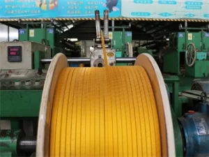
2.4 Fiberglass Braiding
Fiberglass braiding is the core process in fiberglass covered wire manufacturing, mainly including the following steps:
Plying: Combine multiple fiberglass yarns together to form strands for braiding. During the plying process, strand tension and twist must be controlled to ensure strand uniformity and stability during braiding.
Braiding: Cover the conductor surface with strands at specific braiding density and angle using specialized braiding equipment. Braiding density is typically 85%~95%, and braiding angle is typically 30°~60°. Braiding equipment typically uses 16-carrier, 24-carrier, or 32-carrier braiding machines, with more carriers resulting in more uniform braided layers. Braiding speed is typically between tens to hundreds of meters per minute, depending on wire specifications and braiding equipment type.
Overlap Control: During the braiding process, overlap width of fiberglass filaments must be controlled to ensure continuity and uniformity of the insulation layer. Overlap width is typically 1.5~2.5 times the filament diameter; too narrow overlap will cause gaps in the insulation layer, while too wide overlap will increase insulation layer thickness and material cost.
Double/Multi-Layer Braiding: For high voltage class or high mechanical strength requirements, double-layer or multi-layer braiding structures are typically used. Each layer of multi-layer braiding is in opposite directions, which can improve the uniformity and mechanical strength of the insulation layer.
2.5 Structural Characteristics of Fiberglass Braided Layer
The fiberglass braided layer has the following structural characteristics:
Porous Structure: The fiberglass braided layer has certain porosity, typically 30%~50%. Porous structure facilitates impregnating varnish penetration and filling, forming a dense composite insulation layer.
Breathability: The breathability of the fiberglass braided layer facilitates air discharge during winding impregnation treatment, ensuring thorough impregnating varnish penetration.
Flexibility: The fiberglass braided layer has certain flexibility and can adapt to winding bending and twisting processing.
3. Impregnating Insulating Varnish
3.1 Functions of Impregnating Varnish
Impregnating insulating varnish has the following important functions in fiberglass covered wire:
Filling Voids: Fully filling the gaps between fiberglass fibers, forming a dense insulation layer, improving breakdown voltage and insulation resistance.
Moisture Protection: Preventing moisture intrusion into the fiberglass layer, improving moisture resistance.
Enhancing Adhesion: Bonding fiberglass filaments into a whole, improving the mechanical strength and wear resistance of the insulation layer.
Assigning Thermal Class: The thermal resistance of the impregnating varnish determines the final thermal class of fiberglass covered wire.
3.2 Main Impregnating Varnish Types
3.2.1 Polyester Resin Impregnating Varnish
Chemical Composition: With polyester resin as the main film-forming material, typically formed by polycondensation of polyols and polyacids.
Thermal Class: Typically Class B (130℃) or Class F (155℃).
Characteristics: Low cost, good flexibility, suitable for general purposes.
3.2.2 Silicone Resin Impregnating Varnish
Chemical Composition: With silicone resin as the main film-forming material, the main chain structure is silicon-oxygen bonds (Si-O), with bond energy up to 444 kJ/mol.
Thermal Class: Typically Class H (180℃) or Class C (above 200℃).
Characteristics: Excellent high-temperature resistance, good hydrophobicity, suitable for high-temperature environments.
3.2.3 Polyurethane Impregnating Varnish
Chemical Composition: With polyurethane as the main film-forming material, the molecular structure contains a large number of urethane bonds (-NHCOO-).
Thermal Class: Typically Class B (130℃) or Class F (155℃).
Characteristics: Excellent flexibility, suitable for scenarios requiring frequent bending.
3.2.4 Polyimide Impregnating Varnish
Chemical Composition: With polyimide as the main film-forming material, the molecular structure contains a large number of aromatic rings and imide rings.
Thermal Class: Class C (above 240℃).
Characteristics: Highest thermal class, excellent electrical performance, very high cost.
3.2.5 Modified Epoxy Resin Impregnating Varnish
Chemical Composition: With epoxy resin as the main film-forming material, improving its flexibility and thermal resistance by adding modifiers.
Thermal Class: Typically Class F (155℃) or Class H (180℃).
Characteristics: Excellent chemical resistance, strong adhesion.
3.3 Impregnation Process
The impregnation process mainly includes the following steps:
Dip Coating: Immerse the braided wire in the impregnating varnish tank, allowing the varnish to fully penetrate into the fiberglass layer. Dip coating time is typically several seconds to dozens of seconds, depending on wire specifications and varnish viscosity.
Baking: Send the dip-coated wire to an oven for high-temperature curing. The oven is typically divided into preheating zone, curing zone, and cooling zone. Preheating zone temperature is typically 100℃~150℃, used to evaporate volatile matter in the varnish; curing zone temperature is set according to varnish type, typically 180℃~300℃; cooling zone temperature gradually decreases to room temperature.
Secondary Dip Coating: For high thermal class or thick insulation type products, secondary or multiple dip coating and baking may be required to achieve the specified insulation layer thickness.
4. Composite Structural Characteristics
4.1 Three-Layer Composite Structure
Fiberglass covered wire adopts a three-layer composite structure of “conductor + fiberglass braided layer + impregnating varnish”, with each layer working synergistically to form a complete insulation system:
Conductor Layer: Provides conductive function,承担 current transmission task.
Fiberglass Braided Layer: Provides mechanical protection and basic insulation, is the skeleton of the composite structure.
Impregnating Varnish Layer: Fills fiberglass voids, provides electrical insulation and moisture protection, is the binder and function assigner of the composite structure.
4.2 Insulation Layer Thickness
The insulation layer thickness of fiberglass covered wire is typically between 0.2mm~0.8mm, with specific thickness determined by voltage class and operating environment. Insulation layer thickness can be classified into the following types:
Thin Insulation Type: Insulation layer thickness 0.2mm~0.35mm, suitable for low-voltage windings.
Standard Type: Insulation layer thickness 0.35mm~0.55mm, suitable for medium-voltage windings.
Thick Insulation Type: Insulation layer thickness 0.55mm~0.8mm, suitable for high-voltage windings.
4.3 Structural Advantages
The composite structure of fiberglass covered wire has the following advantages:
Synergistic Effect: The high mechanical strength of fiberglass and the high electrical insulation performance of impregnating varnish complement each other, forming a composite insulation system with excellent performance.
Designability: By adjusting fiberglass braiding layers, braiding density, and impregnating varnish type, product performance parameters can be flexibly designed to meet different application needs.
Reliability: The composite structure has a high safety margin; even if local insulation layer is damaged, other parts can still provide effective insulation protection.
5. Conclusion
The structural composition of fiberglass covered wire includes conductor materials (copper or aluminum), fiberglass insulation layer (E-glass, S-glass, or C-glass), and impregnating insulating varnish (polyester resin, silicone resin, polyurethane, polyimide, or modified epoxy resin). The three-layer composite structure works synergistically, endowing the product with excellent high-temperature resistance, mechanical strength, and electrical insulation properties. A deep understanding of the structure and composition of fiberglass covered wire is of great significance for engineering technicians to make correct decisions in the processes of material selection, design, manufacturing, and maintenance.